Introduction to the JYP system
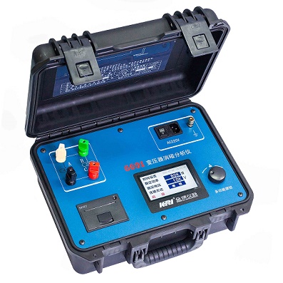
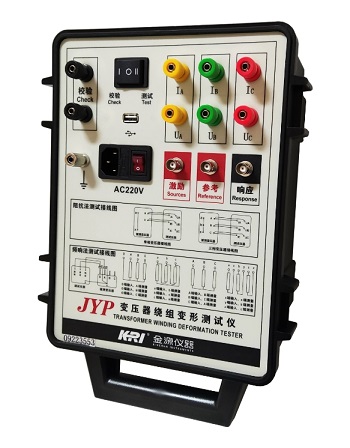
The transformer winding deformation tester is used to test the deformation of transformer windings of power transformers and other special purposes of voltage level of 6kV and above. Power transformers inevitably suffer from the impact or physical impact of various fault short-circuit currents during operation or transportation, and under the strong electrodynamic action generated by short-circuit currents, the transformer windings may lose stability, resulting in permanent deformation phenomena such as local distortion, bulging or displacement, which will seriously affect the safe operation of the transformer. This instrument measures the winding deformation of the transformer by frequency response analysis method according to the national power industry standard DL/T911-2016 and the international electrotechnicalstandard IEC60076-18, which is to detect the amplitude-frequency response characteristics of each winding of the transformer, and compare the test results longitudinally or horizontally, and judge the possible deformation of the transformer winding according to the degree of change in the amplitude-frequency response characteristics.
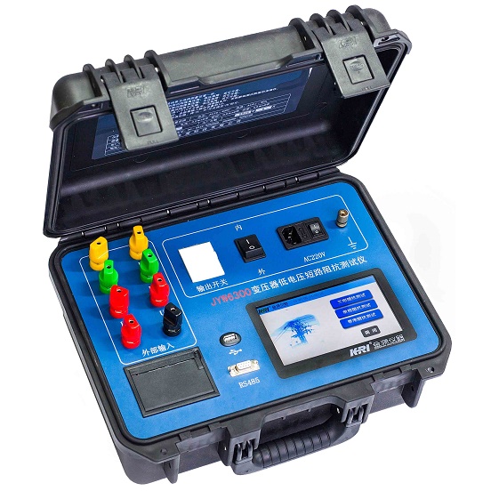
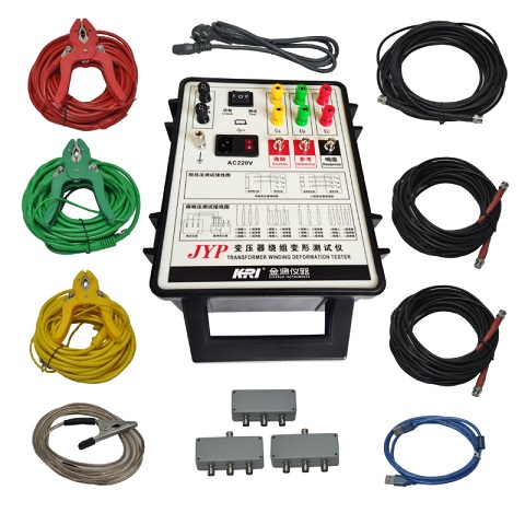
The measurement of low-voltage short-circuit impedance is the basic item of the conventional test project, and the short-circuit impedance value measured before and after the impact of the transformer by the short-circuit current can be preliminarily estimated according to the magnitude of the change. The change in the impedance of the transformer after the short-circuit current impulse from the initially tested low-voltage short-circuit should not be greater than 2%.The system consists of a measurement part and an analysis software part, the analysis part is completed by a laptop, and the measurement part is connected with the laptop through a USB cable

Main technical features
1. The swept frequency method is used to measure the characteristics of the transformer winding, and the distortion of the winding such as twisting, bulging or displacement is accurately measured for the transformer of 6kV and above by detecting the amplitude and frequency response characteristics of each winding without the transformer hanging cover and disassembly.11.The software interface is simple and intuitive, and the menus such as analysis, storage, report export, and printing will automatically pop up the required menus for the next step only after completing the current step, which is more convenient.

Technical Parameter of JYP
Frequency Response Analysis
(FRA)
Measurement speed
For single winding measurement from 100Hz to 1MHz, 1000-point logarithmic sweep test time is 15 seconds
Output voltage
Vpp-20V Automatically adjust during test
Output lmpedance
50Ω
Input impedance
1MQ(response channel built 50Ωmatching resistor)
Sweep range
100Hz-2MHz or 10Hz-10MHz(optional)
Frequency accuracy
0.005%
Sweep mode
Linear or logarithmic, sweep interval and number of points can be set arbitrarily
Measuring wide dynamic range
-100dB~20dB
Curve display
Amplitude-frequency curve/phase-frequency curve
Supply voltage
AC220V±10%
Impedance Method
Voltage measurement range
AC 0.001A ~ 5A
Measurement accuracy
Voltage: 02% ±0.02V, Current: 0.2% ±0.02mA
Power: 0.5% ±0.05W Impedance: 0.5% ±0.05
Supply voltage
AC220V±10%
Kingrun Transformer Instrument Co.,Ltd.


More Transformer Testers from Kingrun