Common Fault Analysis and Diagnosis Technology of Transformer in Power System
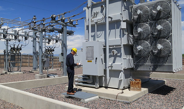
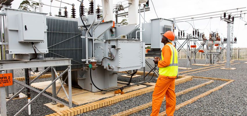
Power transformers are important high-voltage electrical equipment widely used in the power system. Once a fault occurs during operation, it will affect the power supply of the power grid and may cause greater direct economic losses. Although the transformer is currently equipped with multiple protections, due to its own The reason is that the failure rate is still high. Kingrun Instruments summarizes the causes of common transformer faults and commonly used diagnostic techniques through the analysis of the fault field data fed back by customers.
In the process of power transmission and distribution, power transformers are the core of energy conversion and transmission. Serious accidents of transformers will not only cause damage to themselves, but also interrupt power supply, causing huge economic losses. There are various types of transformer faults, and the trend of fault occurrence is also different. Only by fully understanding the actual operating status of the transformer, comprehensively applying various online and historical data, and using various diagnostic techniques, can the hidden faults be discovered in time and the faults can be eliminated. The budding state, thereby ensuring the stable operation of the power system.
1 Analysis of common faults of power transformers
1.1 Conductive circuit and voltage regulator switch failure
The fault of the conductive circuit is mainly caused by the poor contact of the lead, the poor welding of the coil wire joint and the virtual welding. Poor connection of the joints will cause heat or even burn out, which will seriously affect the normal operation of the transformer and the safe power supply of the power grid; the terminals of the lead wires of the transformer are all made of copper, and the aluminum conductors cannot be bolted in outdoor and humid places. Connect with copper terminals. When the water containing dissolved salt, that is, the electrolyte, penetrates between the contact surfaces of copper and aluminum, under the action of the electric coupling, the aluminum is strongly electrically corroded, and the contacts are quickly destroyed, resulting in heat generation and even major accidents.
The failure of the pressure regulating switch is mainly due to the failure of the main contact of the pressure regulating switch, the looseness of the tap lead of the pressure regulating switch, the burning of the contacts of the pressure regulating switch, the insufficient contact pressure of the pressure regulating switch; the poor contact of the switch in the on-load pressure regulating switch , the switch contacts are burnt.
1.2 Insulation failure
The internal insulation of large-scale power transformers is a composite insulation structure composed of insulating materials such as oil, paper, and cardboard, which is continuously aged under electrical, thermal, mechanical and other stresses. Especially for transformers that are close to the design life, the insulation materials of which are accelerated aging under the action of atmosphere and water, which has a huge impact on the safety and reliability of transformer operation. The water inflow of the transformer is damp (including the water ingress of the bushing terminal), the oil quality is poor (the dielectric loss is too large, there are microorganisms, the water content is high), and the local overheating will also cause insulation damage and thermal decomposition of the insulation material.
1.3 Gas production failure
Common gas production faults include discharge and overheating. According to the energy density of discharge, transformer discharge faults are often divided into three types: partial discharge, spark discharge and high-energy discharge. Overheating faults are mainly conductor faults, magnetic circuit faults, poor contacts and connections.
1.3.1 Partial discharge is mainly caused by the presence of air bubbles in the oil or cavities in the solid insulating material, which is likely to cause discharge first in the air gap; the influence of external environmental conditions. If the oil treatment is not completely lowered, air bubbles are formed in the oil, etc. Poor manufacturing quality. If some parts have sharp corners, discharge occurs. Discharge caused by poor contact between metal parts or electrical conductors. Although the energy density of partial discharge is not large, if it develops further, it will form a vicious circle of discharge, which will eventually lead to breakdown or damage of equipment, and cause serious accidents.
1.3.2 Spark discharge caused by floating potential. Components at ground potential, such as silicon steel sheet magnetic shielding and various fastening metal bolts, etc., are loosely connected to the ground and fall off, resulting in floating potential discharge. Poor contact at the end of the high-voltage bushing of the transformer will also form a floating potential and cause spark discharge. The main reason for spark discharge in transformers is the influence of impurities in the oil. Spark discharges can occur at lower voltages.
1.3.3 Arc discharge is a high-energy discharge, which is often caused by insulation breakdown between winding turns, followed by lead breakage or ground flashover and tap changer arcing.
Overheating faults are mainly caused by conductor faults, magnetic circuit faults, poor contacts and connections.
1.4 Winding fault
Winding faults mainly include joint welding, short-circuit, phase-to-phase short-circuit, winding grounding, inter-turn short-circuit, etc. The main cause is that (1) the local insulation of the transformer was damaged during maintenance and manufacturing.
②Long-term overload and poor heat dissipation during the operation of the transformer, sundries fall into the windings, resulting in aging of the insulation; ③The compression is not tight, the manufacturing process is poor, the mechanical strength of the transformer cannot withstand short-circuit impact, the insulation is damaged, and the windings are deformed; ④The windings are damp and damaged. It will cause the insulation expansion to block the oil passage, resulting in partial overheating of the transformer.
1.5 Oil leakage fault
Transformer oil leakage will not only bring great economic losses and environmental pollution to power companies, but also affect the safe operation of transformers. The oil leakage mainly occurs in the oil leakage of the welding seam of the fuel tank. Welding can be carried out directly for the oil seepage at the plane joints. For the oil seepage at the corners and rib joints, it is often difficult to find the leakage point accurately, or after repair welding, it leaks again due to internal stress. For such a seepage point, an iron plate can be added for repair welding, and the iron plate can be cut into a spindle shape for repair welding at the connection on both sides; the iron plate can be cut into a triangle for repair welding according to the actual position of the three-side connection.
Oil seepage from the raised seat or flange of the high-pressure bushing. These parts are mainly due to the improper installation of the rubber gasket, and the flange can be glued and sealed during operation. The leakage of the low-voltage side casing is caused by the stretch of the busbar and the short lead-out of the low-voltage side, and the glue bead is pressed on the thread.
Explosion-proof pipe leaks oil. The explosion-proof pipe is a safety measure to avoid the rupture of the transformer tank due to the internal failure of the transformer resulting in excessive pressure inside the transformer. However, the glass membrane of the explosion-proof tube is easily broken due to vibration during the operation of the transformer, and the glass cannot be replaced in time, so the moisture enters the oil tank, which makes the insulating oil damp, the insulation level is reduced, and the safety of the equipment is endangered. To this end, the explosion-proof pipe is removed and the pressure relief valve can be modified.
1.6 Multi-point ground fault
The iron core of the transformer can only be grounded at one point, and the grounding of two or more points is multi-point grounding. The multi-point grounding operation of the transformer core will cause local short-circuit and overheating of the iron core on the one hand. On the other hand, due to the circulating current generated by the normal grounding wire of the iron core, local overheating of the transformer may occur, and discharge faults may also occur, which endangers the safe operation of the transformer and should be dealt with in time.
 2 Power transformer fault diagnosis method and online monitoring technology
2.1 Transformer fault analysis and diagnosis method
There are many transformer fault analysis and diagnosis methods, mainly including visual inspection method, electrical preventive test method, and dissolved gas analysis method in oil.
2.1.1 Visual inspection method. For the transformer in operation, some obvious fault properties can be directly diagnosed through the daily inspection of the abnormal phenomenon.
2.1.2 Electrical preventive test method. This test method is the main diagnostic method for transformers, and its effectiveness is a decisive factor for the accuracy of the diagnostic results. Obtaining reliable and accurate test results through various effective tests is the basic premise for correct diagnosis of transformer faults.
2.1.3 Analysis of dissolved gas in oil. The type of dissolved gas in the oil has a corresponding relationship with the nature of the internal fault of the transformer. Therefore, this method is very effective for diagnosing the internal fault of the transformer.
2.2 Transformer online monitoring technology
The purpose of on-line monitoring of transformers is to identify the status of transformers by collecting and analyzing characteristic signals of transformers, in order to detect the initial faults of transformers and monitor the development trend of fault status. At present, the online monitoring of power transformers is one of the most studied objects in the world, and many different methods have been proposed. Dissolved Gas Analysis Technology in Oil. Since different faults inside the transformer will produce different gases, the purpose of transformer insulation diagnosis can be achieved by analyzing the composition, content, gas production rate and relative percentage of the gases in the oil.
Partial discharge online monitoring technology. Partial discharges (PDs) can occur due to excessive local field strengths when transformers fail internally or operate under harsh conditions. Apparent changes in PD levels and their growth rates can indicate changes that are taking place inside the transformer or reflect voids, metal particles, and air bubbles, etc., of solid insulation in the insulation due to certain defect states.
Vibration analysis method. Vibration analysis is an effective method widely used to monitor such transformer faults. By monitoring and analyzing the vibration signal of the transformer, the purpose of monitoring the state of the transformer is achieved.
Infrared temperature measurement technology. Infrared thermal imaging technology uses an infrared detector to receive the infrared radiation signal of the measured target, amplify it, convert it into a standard video signal, and then display the infrared thermal image through a TV screen or monitor. When the transformer leads are in poor contact, overloaded operation, etc., it will cause local overheating of the conductive circuit, and the multi-point grounding of the iron core will also cause
Frequency response analysis method. Frequency response analysis is an effective method for judging whether the transformer winding or lead structure is offset. The mechanical displacement of the winding will produce a slight change in inductance or capacitance, and the frequency response method is used to monitor the state of the transformer winding by measuring this slight change.
Winding temperature indication. Winding temperature indicators are used to monitor the temperature of the transformer windings, give out-of-limit alarms, and initiate protection trips when needed. At present, a new technology for temperature monitoring of large transformer windings has been developed, that is, an optical fiber is embedded in the transformer winding to directly measure the real-time temperature of the winding, thereby improving the predictive modeling technology of the transformer and achieving the purpose of monitoring the temperature status of the transformer winding in real time. .
3 Conclusion
With the rapid development of power system automation, the reliability of power supply is increasing day by day. In order to meet this demand, a more intelligent online monitoring system must be developed. As shown in Figure 1. This online intelligent monitoring system includes sensors of various dynamic performance monitoring devices of transformers. Some of the electrical signals collected by various sensors are processed by amplifiers and conditioning circuits and then connected to analog-to-digital conversion circuits, and some are processed by analog-digital acquisition cards. Some of them are connected to the industrial computer after the interface circuit, and the data is processed by the front computer, and then sent to the background central processing unit transformer fault real-time diagnosis system for diagnosis and analysis, and the monitoring results are obtained, and the abnormal conditions of the transformer are monitored and alarmed. This monitoring system is organically combined with the transformer itself to comprehensively analyze and diagnose transformer faults, which not only improves the level of real-time monitoring and computer-aided diagnosis of transformer operating conditions, but also helps users achieve the goal of more reliable and economical equipment operation.
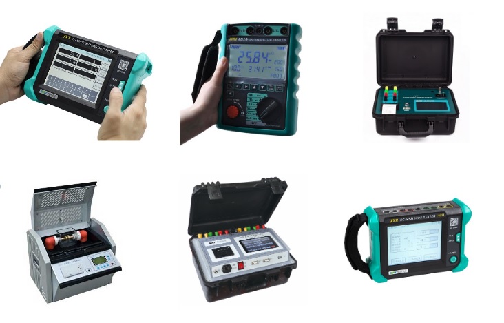
Kingrun Series Power Transformer Testers:
2 Power transformer fault diagnosis method and online monitoring technology
2.1 Transformer fault analysis and diagnosis method
There are many transformer fault analysis and diagnosis methods, mainly including visual inspection method, electrical preventive test method, and dissolved gas analysis method in oil.
2.1.1 Visual inspection method. For the transformer in operation, some obvious fault properties can be directly diagnosed through the daily inspection of the abnormal phenomenon.
2.1.2 Electrical preventive test method. This test method is the main diagnostic method for transformers, and its effectiveness is a decisive factor for the accuracy of the diagnostic results. Obtaining reliable and accurate test results through various effective tests is the basic premise for correct diagnosis of transformer faults.
2.1.3 Analysis of dissolved gas in oil. The type of dissolved gas in the oil has a corresponding relationship with the nature of the internal fault of the transformer. Therefore, this method is very effective for diagnosing the internal fault of the transformer.
2.2 Transformer online monitoring technology
The purpose of on-line monitoring of transformers is to identify the status of transformers by collecting and analyzing characteristic signals of transformers, in order to detect the initial faults of transformers and monitor the development trend of fault status. At present, the online monitoring of power transformers is one of the most studied objects in the world, and many different methods have been proposed. Dissolved Gas Analysis Technology in Oil. Since different faults inside the transformer will produce different gases, the purpose of transformer insulation diagnosis can be achieved by analyzing the composition, content, gas production rate and relative percentage of the gases in the oil.
Partial discharge online monitoring technology. Partial discharges (PDs) can occur due to excessive local field strengths when transformers fail internally or operate under harsh conditions. Apparent changes in PD levels and their growth rates can indicate changes that are taking place inside the transformer or reflect voids, metal particles, and air bubbles, etc., of solid insulation in the insulation due to certain defect states.
Vibration analysis method. Vibration analysis is an effective method widely used to monitor such transformer faults. By monitoring and analyzing the vibration signal of the transformer, the purpose of monitoring the state of the transformer is achieved.
Infrared temperature measurement technology. Infrared thermal imaging technology uses an infrared detector to receive the infrared radiation signal of the measured target, amplify it, convert it into a standard video signal, and then display the infrared thermal image through a TV screen or monitor. When the transformer leads are in poor contact, overloaded operation, etc., it will cause local overheating of the conductive circuit, and the multi-point grounding of the iron core will also cause
Frequency response analysis method. Frequency response analysis is an effective method for judging whether the transformer winding or lead structure is offset. The mechanical displacement of the winding will produce a slight change in inductance or capacitance, and the frequency response method is used to monitor the state of the transformer winding by measuring this slight change.
Winding temperature indication. Winding temperature indicators are used to monitor the temperature of the transformer windings, give out-of-limit alarms, and initiate protection trips when needed. At present, a new technology for temperature monitoring of large transformer windings has been developed, that is, an optical fiber is embedded in the transformer winding to directly measure the real-time temperature of the winding, thereby improving the predictive modeling technology of the transformer and achieving the purpose of monitoring the temperature status of the transformer winding in real time. .
3 Conclusion
With the rapid development of power system automation, the reliability of power supply is increasing day by day. In order to meet this demand, a more intelligent online monitoring system must be developed. As shown in Figure 1. This online intelligent monitoring system includes sensors of various dynamic performance monitoring devices of transformers. Some of the electrical signals collected by various sensors are processed by amplifiers and conditioning circuits and then connected to analog-to-digital conversion circuits, and some are processed by analog-digital acquisition cards. Some of them are connected to the industrial computer after the interface circuit, and the data is processed by the front computer, and then sent to the background central processing unit transformer fault real-time diagnosis system for diagnosis and analysis, and the monitoring results are obtained, and the abnormal conditions of the transformer are monitored and alarmed. This monitoring system is organically combined with the transformer itself to comprehensively analyze and diagnose transformer faults, which not only improves the level of real-time monitoring and computer-aided diagnosis of transformer operating conditions, but also helps users achieve the goal of more reliable and economical equipment operation.
Kingrun Series Power Transformer Testers:
765
