The insulation resistance of a transformer refers to the resistance of its electrical insulation performance between the windings and the ground, between the windings, or between the windings and other non-conductive parts. It is typically measured using an insulation resistance tester, and the unit is ohms (Ω).
Definition of Transformer Insulation Resistance Measurement:
High voltage winding to low voltage winding and outer casing insulation resistance**: (Primary winding to secondary winding and outer casing)
Low voltage winding to high voltage winding and outer casing insulation resistance**: (Secondary winding to primary winding and outer casing)
Why Test the Insulation Resistance of Transformers?
1. Ensure Equipment Safety**: The transformer’s insulation system prevents current leakage, protecting both equipment and operators from electric shocks. A low insulation resistance may indicate aging or damage to the insulation system, which could lead to equipment failure, short circuits, or even fire hazards.
2. Prevent Transformer Failures**: Testing insulation resistance helps identify potential insulation problems during operation. Early maintenance or replacement of insulation materials can prevent sudden failures.
3. Ensure Long-Term Reliable Operation**: Over time, transformers are affected by temperature, humidity, and electrical stress. Insulation resistance testing helps assess the transformer’s condition, ensuring it can continue operating reliably under normal conditions.
Standards for Transformer Insulation Resistance Acceptance Values:
1. Comparison with Previous Measurements**: The insulation resistance value obtained this time, when converted to the same temperature as the previous measurement, should not be more than 30% lower than the previous value.
2. Absorption Ratio (R60/R15): The ratio of insulation resistance at 60 seconds to that at 15 seconds should be at least 1.3 times or greater when measured between 10°C and 30°C.
3. Minimum Acceptable Insulation Resistance for Transformers with a Testing Voltage of 10kV**: The minimum acceptable value of insulation resistance varies with temperature.
Based on the measured insulation resistance value, a preliminary estimation of the transformer’s insulation condition can be made. This also helps determine whether other insulation tests involving applied voltages can continue. In preventive electrical equipment testing, the insulation resistance values of most high-voltage electrical equipment are not strictly specified, except for certain simple structures or low-voltage devices. These values are often self-defined, considering factors such as transformer material selection, product structure, manufacturing processes, and environmental conditions like temperature and humidity, which make it difficult to determine a unified allowable insulation resistance value. The minimum allowable insulation resistance value for oil-immersed power transformer windings without factory test reports, as provided by KINGRUN, is as follows for reference:
Permissible value of insulation resistance of oil-immersed power transformer (MΩ)
Temp. ℃
Voltage Grade
10
20
30
40
50
60
70
80
3~10kV
450
300
200
130
90
60
40
25
20~35kV
600
400
270
180
120
80
50
35
60~220kV
1200
800
540
360
240
160
100
70
Note:
1. In the same transformer, the high and low voltage windings have the same standards
2. 13.8kV and 15.7kV can be classified as 3~10kV, and 18kV and 44kV can be classified as 20~35kV.The insulation resistance of the winding should be measured in turn between each winding and the ground and other windings. The lead ends of the measured winding should be short-circuited, and the other non-measured windings should be short-circuited to ground. The order and location are shown in the table below:
Item
Two-winding transformer
Three-winding transformer
Tested winding
Grounding Point
Tested winding
Grounding Point
1
LV Side
Shell and HV
LV Side
Shell、H、MV
2
HV Side
Shell and LV
MV Side
Shell、H、LV
3
-
-
HV Side
Shell、M、LV
4
(HV and LV)
(Shell)
(HV and MV)
(Shell and LV)
5
-
-
(H、M、LV)
(Shell)
Note:
1. Items 4 and 5 are for transformers with a rating of 15,000 kVA and above.
2. The parts in parentheses should only be measured when necessary.
When measuring insulation resistance, the oil should be circulated and allowed to settle for a period of time before measurement. For transformers rated 3 to 10 kVA, the waiting time should be at least 5 hours. For transformers rated 800 kVA and above, the waiting time should be at least 20 hours.
Absorption Ratio: "Transformer Preventive Testing" requires that it should not be lower than 1.3 (at 10–30°C). Some "Manufacture Transformer Preventive Testing" specify that for transformers rated 35 kV and above, the absorption ratio should be measured, and it should not be lower than 1.3 at normal temperature. If the insulation resistance is greater than 10,000 MΩ, the absorption ratio should not be lower than 1.1.
Polarization Index: "Transformer Preventive Testing" requires that it should not be lower than 1.5. Some "Manufacture Transformer Preventive Testing" specify that if the absorption ratio is low, the polarization index should be measured, and it should not be lower than 1.5. If the insulation resistance is greater than 10,000 MΩ, the polarization index should not be lower than 1.3.
Since the absorption ratio may have uncertainties in assessing the insulation condition, especially for large transformers, the use of the Polarization Index (PI) is considered more reliable for determining insulation condition.
Basis for Polarization Index Evaluation:
Status
Polarization Index
Status
Polarization Index
Dangerous
<1.0
Fair
1.25 ~ 2.0
Poor
1.0 ~ 1.1
Good
>2.0
Suspicious
1.1 ~ 1.25
Apart from cases where the measured insulation resistance is very low, and the test personnel deem the insulation to be defective, generally, test personnel should compare the insulation resistance values of different phases under the same conditions, or compare the results of multiple tests of the same equipment (converted to the same temperature, if possible). Comprehensive judgment should be made in conjunction with other test results. If necessary, the individual components of the device can be measured separately, and unmeasured parts should be connected to a shielding terminal to facilitate fault location analysis.
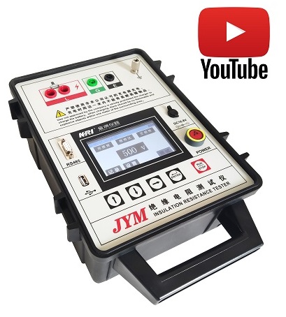
JYM insulation resistance tester

Kingrun Transformer Instrument Co.,Ltd.


More Transformer Testers from Kingrun