What is insulation resistance?
Insulation resistance: DC voltage is applied to the dielectric. After a certain period of polarization, the corresponding leakage current flowing through the dielectric is called insulation resistance.
Insulation resistance is the most basic insulation indicator for electrical equipment and electrical wiring. For the handover test of low-voltage electrical installations, the insulation resistance of the motor, power distribution equipment and distribution lines at normal temperature shall not be less than 0.5 MΩ (for operation equipment and wiring, the insulation resistance shall not be less than 1 MΩ/kV). The insulation resistance of low-voltage electrical appliances and their connecting cables and secondary circuits should generally not be lower than 1MΩ; in relatively humid environments, it should not be lower than 0.5MΩ; the insulation resistance of small-circuit small bus bars should not be lower than 10 MΩ. The insulation resistance of Class I handheld power tools should not be less than 2MΩ.
What is the grounding resistance?
The grounding resistance is the resistance encountered when a current flows from the grounding device into the ground and then flows through the earth to another grounding body or spreads to a distant place. The unit of measurement is Ω. The size of the grounding resistance can reflect the degree of contact between the electrical device and the "ground" and reflect the scale of the grounding grid.
The grounding resistance measurement method includes two-wire method, three-wire method, four-wire method, single-clamp method and double-clamp method. Each of the five methods has its own characteristics. When actually measuring, try to select the correct method and measuring tester to make the measurement. The results are accurate.

What is DC winding resistance?
DC resistance is mainly for DC resistance testing of inductive loads such as transformers, motors, CT/PT, etc. The measurement unit is mΩ. For example, the measurement of the DC resistance of the winding of the transformer is a convenient and effective test to investigate the connection condition of the winding insulation and the current loop. It can reflect the welding quality of the winding, the winding turn-to-turn short circuit, the winding break or the lead wire break, the tap changer and faults such as poor wire contact, in fact, it is also an effective means to judge whether the DC resistance of each phase winding is balanced and whether the voltage regulating switch gear position is correct.
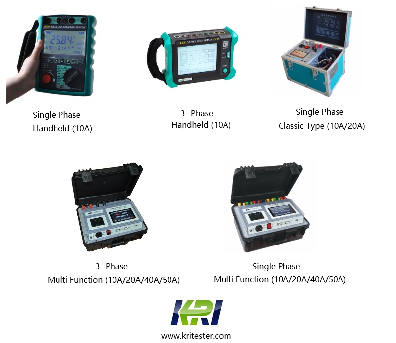
The DC resistance measurement methods include: current-voltage method, DC bridge method, and simultaneous compression of three-phase windings. Now DC resistance testers are all using the DC bridge method, which requires the test current to be no less than 1A, and the measurement resistance value is small. High, test currents are common: 1A, 3A, 10A, 20A, 40A, 50A, 100A, these are only used for single-phase measurements. For three-phase simultaneous measurement, the JYR-10S/20S and JYR-40S/50S three-channel DC resistance testers are available.
What is contact resistance?
The contact resistance is a parameter that characterizes whether the connection of the conductive loop is good, and the unit of measurement is μΩ. Each type of high voltage circuit breaker specifies a range of values. If the loop resistance exceeds the specified value, it is likely that the connection of the conductive loop is poor. In the case of high current operation, the local temperature rise at the contact failure is increased. In severe cases, even the vicious cycle causes oxidative burning loss, and the circuit breaker used for high current operation needs to pay more attention.
Contact resistance measurement, measurement by bridge method, DC voltage drop method is not allowed. And the test current is greater than or equal to 100A. The Contact Resistance Tester is used to measure the contact resistance of switchgear such as high-voltage switch and on-load switch, and can directly reflect the contact condition of the switch contact.
Related Articles:
The Most Complete Transformer Vector Group Collection with Winding Connection Diagrams
How Important is Transformer DC Winding Resistance?
Top 6 transformer winding resistance testers Worldwide (Including Prices)
How should Winding Resistance be Tested Differently on CT and PT?
What is the Difference between DC Resistance and Insulation Resistance and How to Test Them?
8 Tips to Improve the Accuracy of DC Resistance Measurement
Why is the Tested Winding Resistance Always Inaccurate? You May Have Overlooked These 6 Key Points
Kingrun Series DC winding resistance testers

Kingrun Transformer Instrument Co.,Ltd.

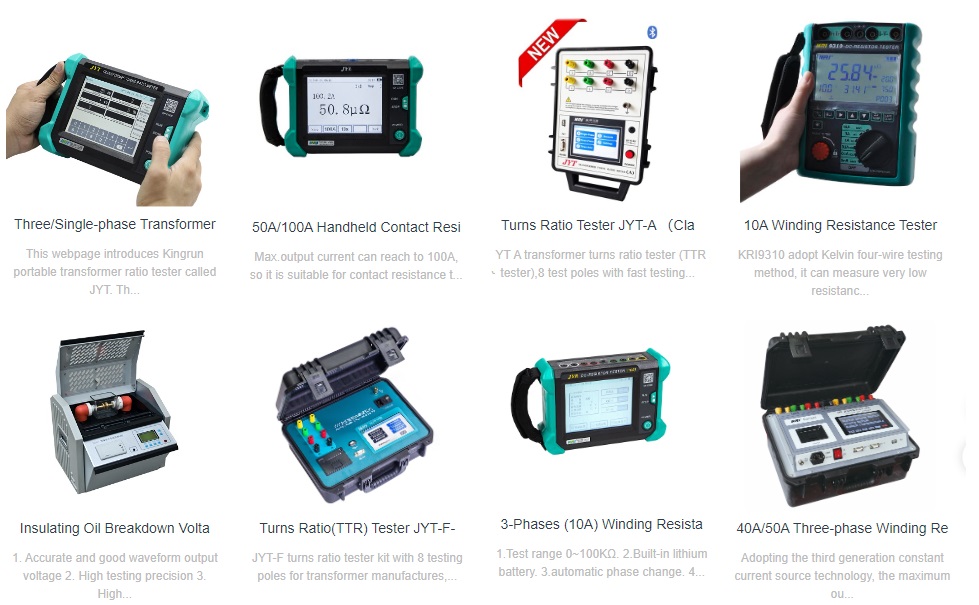
More Transformer Testers from Kingrun
