
What is Transformer Winding?
When it comes to the transformer winding, it is necessary to mention the internal structure of the transformer. For a single-phase transformer, the single-phase transformer has two windings wound together on a closed core. The winding connected to the power supply is called the primary winding. As shown in the figure U1, I1, etc., the windings with the load necklace are called the secondary windings U2 and I2, and the middle is the iron core.
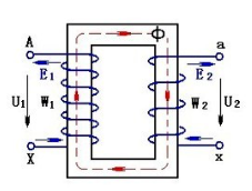
When the original winding of the transformer is applied with the alternating voltage u1, an alternating current i1 is generated in the primary winding, and this current generates an alternating magnetic flux Φ in the iron core because the primary and secondary windings are on the same core, so When the magnetic flux Φ passes through the secondary winding, an induced electromotive force e2 (ie, a transformer voltage) is generated at the secondary side of the transformer, and the magnitude of the induced electromotive force in the transformer is proportional to the number of turns of the winding, the magnitude of the magnetic flux, and the frequency of the power source. The volume of the transformer is related to the voltage.
Measuring method of transformer winding winding resistance
The measurement of the transformer winding is also called the DC resistance measurement of the transformer because the DC current is applied. The measurement method of the transformer winding is actually the DC resistance under the static of the internal winding. Under static conditions, the primary or secondary winding is given. It is also called the high-voltage side and the low-voltage side. It applies a certain rated current to make the core saturated, and calculates the resistance value of the winding. The degree of saturation of the core is different for different voltage levels, but the measurement of the winding resistance of the transformer winding. The method is basically the same. The method is: input the processed DC power into the high voltage side or the low voltage side of the transformer, wait for the core to be saturated, and the core needs saturation for a certain time. Depending on the current of the selected test equipment, the current is larger. The faster the saturation speed, on the contrary, the lower the test efficiency.
Selection of transformer winding winding resistance
As highlighted above, the efficiency of the DC resistance test depends on the saturation speed of the transformer core. So how do we change the DC resistance measurement of the transformer?
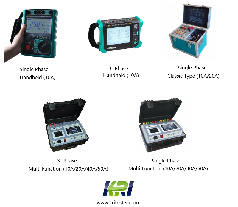
Selection of transformer DC resistance In general, the magnitude of DC current is directly proportional to the capacity of the transformer. The higher the voltage means the flux and the number of turns, the core is naturally large, and we usually recommend 10kv power. For the transformer in the system, it is recommended to use the 5A DC resistance tester. The transformer in the 110kv power system is recommended to use the 5A-20A DC resistance tester for measurement. If it is cheaper, it is not a small one, but the measurement speed. Very slow and data is unstable.
Related Articles:
The Most Complete Transformer Vector Group Collection with Winding Connection Diagrams
How Important is Transformer DC Winding Resistance?
Top 6 Transformer winding resistance testers Worldwide (Including Prices)
How should Winding Resistance be Tested Differently on CT and PT?
What is the Difference between DC Resistance and Insulation Resistance and How to Test Them?
8 Tips to Improve the Accuracy of DC Resistance Measurement
Why is the Tested Winding Resistance Always Inaccurate? You May Have Overlooked These 6 Key Points
Kingrun Series DC winding resistance testers

Kingrun Transformer Instrument Co.,Ltd.


