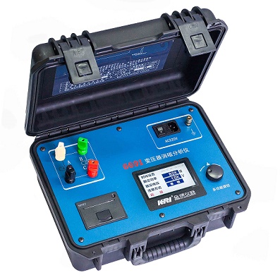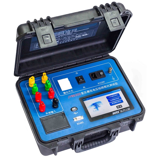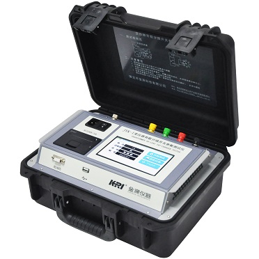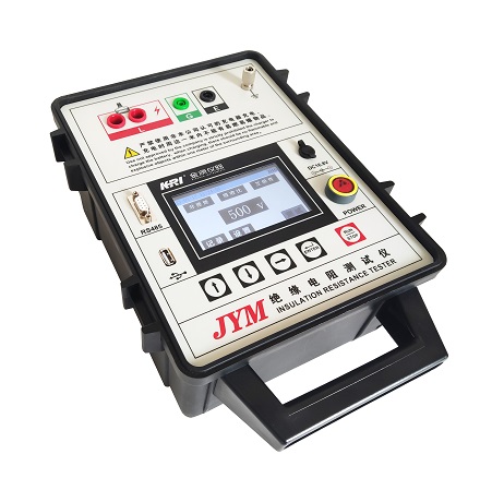
The JYM insulation resistance tester is used for measuring insulation resistance in the field. This instrument features a built-in negative high-voltage power supply, high output power, and a strong load capacity, making it suitable for measuring the insulation resistance of samples with high capacitance, such as power transformers and cables. It employs digital filtering technology for automatic intelligent measurements, ensuring stable data even in the presence of strong interference. Measurement results are displayed on a large LCD screen and can be printed using a microprinter. The instrument can be powered in two ways: through an external adapter or an internal battery, making testing convenient.
Features:
Test voltage: 500V, 1000V, 2500V, 5000V, 10000V (optional) five output voltage levels.
Voltage accuracy: ± (set value×2%+10V) (when the resistance under test is below 10MΩ, the output voltage will decrease, down to 45% of the set value).
Short circuit current: not less than 30mA (this index far exceeds the traditional megohmmeter, direct short circuit or short circuit test voltage during measurement may cause instrument protection, special attention should be paid to safety).
Measuring range: 100kΩ~10TΩ
Measurement accuracy:
5% at 100kΩ~10GΩ (test voltage is not less than 250V).
5% at 10GΩ~100GΩ (test voltage not less than 2500V)
10% at 100GΩ~5TΩ (test voltage not less than 5000V)
10% at 100GΩ~10TΩ (test voltage not less than 10000V) (optional)
Anti-interference: power frequency 5mA
Measurement method: insulation resistance / absorption ratio / polarization index
Wiring method: grounded or non-grounded
Fast discharge: Yes
Measurement time: insulation resistance automatic measurement (press the run/stop button to stop), absorption ratio 60 seconds, polarization index 10 minutes
Input power: external adapter (180V~270VAC).
Computer interface: standard RS232 interface, optional wireless Bluetooth or wireless WIFI communication
Printer: Optional Bluetooth printer.
Ambient temperature: -10°C~50°C
Relative humidity: <90%, no condensation.

Main Functions of JYM Insulation Tester:
1. Strong anti-interference ability.
Using digital filtering technology, it can still accurately measure under the power frequency 5mA interference current, and the test data is stable, which is suitable for insulation resistance test in the field.
2. Built-in positive or negative high voltage output power supply
The user can choose to configure the positive or negative high voltage output according to the needs.
3. Large short-circuit current
Not less than 30mA (this index far exceeds the traditional microohmmeter, direct short circuit or short circuit test voltage during measurement may cause instrument protection, special attention should be paid to safety).
4. Strong load capacity
The current output of the high-voltage power supply is not less than 6 mA at the 5000V voltage level.
The high voltage power supply has a current output of not less than 3 mA at a voltage level of 10000V.
5. Rapid discharge
The instrument is equipped with an independent discharge circuit, and when testing capacitive samples, the instrument can automatically and quickly discharge the samples.
Note: In order to ensure safety, the test should still be shorted with a short-circuit rod after the measurement.
6. Multi-level security protection to ensure the safety of people and equipment.
High voltage protection: short circuit, breakdown or high voltage current fluctuation of the sample, cutting off the output at high speed.
7. Chinese and English menus are optional, large screen backlit LCD display.
8..Optional thermal printer.
9. With USB interface.
10. With computer interface.
Through this interface, measurement, data processing and report output are realized. One computer can control 32 instruments and can be integrated into the integrated high-voltage test vehicle.
11. Power supply :JYM insulation resistance tester provides two power supply modes, external adapter (180V~270VAC mains power or generator power supply), internal power supply for lithium battery. When the external power supply is turned on, the instrument automatically selects the AC power supply mode for testing, and when no external adapter is connected, the instrument uses internal battery power supply.

Permissible value of insulation resistance of oil-immersed power transformer (MΩ)
|
Temp. ℃ Voltage Grade |
10 |
20 |
30 |
40 |
50 |
60 |
70 |
80 |
|
3~10kV |
450 |
300 |
200 |
130 |
90 |
60 |
40 |
25 |
|
20~35kV |
600 |
400 |
270 |
180 |
120 |
80 |
50 |
35 |
|
60~220kV |
1200 |
800 |
540 |
360 |
240 |
160 |
100 |
70 |
Note:
1. In the same transformer, the high and low voltage windings have the same standards
The insulation resistance of the winding should be measured in turn between each winding and the ground and other windings. The lead ends of the measured winding should be short-circuited, and the other non-measured windings should be short-circuited to ground. The order and location are shown in the table below:
|
Item |
Two-winding transformer |
Three-winding transformer |
||
|
|
Tested winding |
Grounding Point |
Tested winding |
Grounding Point |
|
1 |
LV Side |
Shell and HV |
LV Side |
Shell、H、MV |
|
2 |
HV Side |
Shell and LV |
MV Side |
Shell、H、LV |
|
3 |
- |
- |
HV Side |
Shell、M、LV |
|
4 |
(HV and LV) |
(Shell) |
(HV and MV) |
(Shell and LV) |
|
5 |
- |
- |
(H、M、LV) |
(Shell) |
Note:
1. Items 4 and 5 are for transformers with a rating of 15,000 kVA and above.
2. The parts in parentheses should only be measured when necessary.
When measuring insulation resistance, the oil should be circulated and allowed to settle for a period of time before measurement. For transformers rated 3 to 10 kVA, the waiting time should be at least 5 hours. For transformers rated 800 kVA and above, the waiting time should be at least 20 hours.
Absorption Ratio: "Transformer Preventive Testing" requires that it should not be lower than 1.3 (at 10–30°C). Some "Manufacture Transformer Preventive Testing" specify that for transformers rated 35 kV and above, the absorption ratio should be measured, and it should not be lower than 1.3 at normal temperature. If the insulation resistance is greater than 10,000 MΩ, the absorption ratio should not be lower than 1.1.
Polarization Index: "Transformer Preventive Testing" requires that it should not be lower than 1.5. Some "Manufacture Transformer Preventive Testing" specify that if the absorption ratio is low, the polarization index should be measured, and it should not be lower than 1.5. If the insulation resistance is greater than 10,000 MΩ, the polarization index should not be lower than 1.3.
Since the absorption ratio may have uncertainties in assessing the insulation condition, especially for large transformers, the use of the Polarization Index (PI) is considered more reliable for determining insulation condition.
Basis for Polarization Index Evaluation:
Status
Polarization Index
Status
Polarization Index
Dangerous
<1.0
Fair
1.25 ~ 2.0
Poor
1.0 ~ 1.1
Good
>2.0
Suspicious
1.1 ~ 1.25
Kingrun Transformer Instrument Co.,Ltd.


More Transformer Testers from Kingrun