The contact resistance tester designed according to the conventional design principle is found in the field test, and there is a common problem: when the voltage wiring circuit of the tester has poor contact or open circuit, the tester will also display a value, and the following type conditions will appear at this time:
(1) The voltage contact is open, and there is no strong electric field interference at the test site. In this case, since the differential mode voltage input by the amplifier is basically 0, the test value displayed by the instrument is close to 0. If the tester has enough field test experience, It can be judged that the voltage contact test line of the instrument is abnormal, and the final correct test result can be obtained after the abnormal voltage contact test line of the instrument is eliminated; Test, replace or repair the instrument, delay the power outage time, and bring unnecessary trouble to the test work.
(2) The voltage circuit is in poor contact. In most cases, the terminals of the circuit breaker will produce oxide film or oil film on the outer surface of the terminal block after long-term operation. When the voltage test clamp of the contact resistance meter is clamped to such a terminal block, it may be If there is poor contact, both the voltage test wire clamp itself will also have a certain contact resistance. When the contact resistance value reaches the internal resistance value of the voltage sampling circuit, it will have a serious impact on the test results.
(3) The voltage contact is open circuit or poor contact (when the circuit is open, the visible contact resistance R1 is infinite), and there is strong electromagnetic interference at the test site, such as the bus-bar is live, at this time, the live bus-bar passes through the air-medium capacitor, which interferes with the two sides of the tester. A voltage test line, due to the effect of interference, differential mode voltage appears at both ends of the voltage collection line of the contact tester.
If the interference is large, the contact resistance tester will display a much larger value than the resistance value of the test object. At this time, if the tester has enough field test experience, he may be able to judge the abnormality of the test result, which can attract attention and finally get correct test results. However, if the testers do not have enough experience, they may misjudge that the switch contact resistance value exceeds the standard, and may adopt the method of power failure maintenance to deal with the defects, causing unnecessary losses to power production.
If the intensity of the interference is not very large, the displayed value of the A-contact resistance tester is just within the acceptable resistance range of the circuit breaker. This situation is the same as the result of the situation "(2) The voltage circuit is in poor contact", which will also cause misjudgment. .
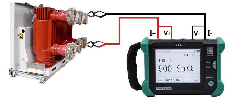
The principle of JYL contact resistance tester (thermistor tester) is to use a typical four-wire measurement method, which effectively eliminates the influence of the test line on the measurement results. The built-in power supply provides 50A/100A test current, and press the measurement button. At the same time, the high-frequency switching power supply outputs 50A/100A test current, and the sampling circuit starts sampling at the same time. The obtained signal is amplified by the amplifier, and the analog signal is converted into a digital signal by the A/D converter, and then the data is filtered by the microprocessor. , operation, processing, and finally send the display to show the current and resistance value measured this time. When the current test contact is disconnected or has poor contact, the instrument will judge the current contact with poor contact or open circuit according to the voltage on the current shunt. JYL contact resistance tester adopts new power supply technology, which has the characteristics of large output current, wide range, rapid measurement, small size, convenient use and high measurement accuracy. It is an ideal device for measuring substation contact equipment and high-voltage switches.