Transformer Preventive Test Items and Reference Standards
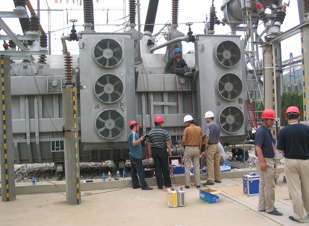
Tests must be carried out after the transformer is overhauled and installed, and a preventive test should be carried out on the transformer between the two overhauls. In this way, the fault of the transformer can be effectively checked, the type of fault can be determined, and the safety of the transformer can be ensured to a certain extent.
Transformer DC Resistance Test and Calculation
Measuring the DC resistance of the transformer winding is a very important test item, and its order is the second in the transformer test item. The DC resistance of the transformer refers to the DC resistance value of each phase winding. The purpose of measuring the DC resistance is to check whether there is an inter-turn short circuit inside the three-phase winding. Because if there is a phase-to-phase short circuit inside the transformer, the short-circuit current value is very large, it is easy to burn the transformer, the phenomenon of the fault is also obvious, and the appearance is easy to judge. However, if there is a short circuit between the turns of one of the phases, the short-circuit current value is very small, and the gas protection of the transformer will trip, but it is difficult to see whether the transformer itself is faulty from the appearance of the transformer. By measuring the DC resistance of each phase, it is easy to judge whether an inter-turn short circuit occurs internally by comparing the three-phase resistance values: if the resistance value is very different, the possibility of inter-turn short circuit fault is very large; if it is basically similar, this can be ruled out. possibility of failure. According to the structure of the transformer, the windings are almost insulated by the insulating medium of the insulated wire itself. If there is a defect in the insulation treatment, and the transformer has a large load, the weak insulation is likely to cause inter-turn short circuit. Therefore, the purpose of measuring the DC resistance is to judge whether the transformer is short-circuited between turns, which is convenient for troubleshooting.
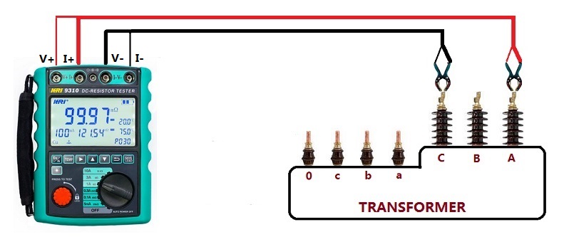
The standard for measuring the DC resistance of the transformer coil is: For transformers above 1600kVA, the difference between the winding resistances of each phase should not be greater than 2% of the average value of the three-phase, and the difference between the windings without the neutral point lead wire should not be greater than the three-phase difference. 1% of the average value. For transformers of 1600kVA and below, the phase-to-phase difference is generally not more than 4% of the three-phase average value, and the line-to-line difference is generally not more than 2% of the three-phase average value. The change should not be greater than 2%. Measuring the DC resistance of a transformer is different from measuring the general resistance, because the transformer winding has a huge inductance. Measurement methods include current, voltmeter and balanced bridge methods. Due to the development of power electronic test equipment technology, transformer DC resistance testers are generally used for measurement.
The advantages of the transformer DC resistance tester are:
① It can automatically select the output current and the output current is large.
② Wide measurement range (0~50Ω), can measure inductive DC resistance, such as transformers and transformers.
③ Display electronic screen, display data is clear and easy to read. Therefore, it has been widely used in the market.
Transformer Turns Ratio Test(TTR)
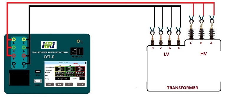
When the transformer is under no-load condition, the ratio of the voltage U1 of the high-voltage winding to the voltage of the low-voltage winding U2 is the voltage ratio. The transformation ratio of a three-phase transformer is usually calculated according to the line voltage. The transformation ratio test is to apply a voltage on one side of the transformer, measure the voltage on the other side with a meter or instrument, and then calculate the transformation ratio according to the measurement results. The purpose of the transformer ratio test is to check whether the number of turns of the winding is correct, check the status of the tap changer, check whether the winding has a metallic short circuit between layers (turns), etc., to provide a basis for whether the transformer can be put into operation or parallel operation. There are voltage measurement method and bridge method for on-site determination of voltage ratio.
In the process of power transformer production, user handover and maintenance test, transformer ratio test is a must-do item. This can effectively supervise the quality of transformer products during delivery and use, and prevent transformer inter-turn short circuit, open circuit, connection error, internal fault or contact fault of the voltage regulating switch. The transformer ratio tester is now used for measurement, which has the characteristics of easy operation, complete functions, and stable and reliable data. It can meet the needs of various large, medium and small transformer ratio group tests. Analysis and judgment of test results:
(1) Compared with the nameplate value, the voltage ratio of each phase connector should not be significantly different and conform to the law.
(2) For transformers whose voltage is less than 35kV and whose voltage ratio is less than 3, the allowable deviation of the voltage ratio is ±1%. All other transformers: The allowable deviation of rated tap voltage ratio is ±0.5%, and the voltage ratio of other taps should be within 1/10 of the transformer impedance voltage value (%), but not more than ±1%.
Transformer Insulation Resistance Test
When measuring the insulation resistance of windings, measure the insulation resistance values of each winding to ground and other windings in turn. The lead ends of the winding under test should be short-circuited, and the other non-test windings should be short-circuited to ground. The order and specific parts of the measurements are shown in the table.
|
Sequence
|
Double winding transformer
|
Three winding transformer
|
|
Tested Winding
|
Ground Point
|
Tested Winding
|
Ground Point
|
|
1
|
LV
|
Shell & HV
|
LV
|
Shell & HV/MV
|
|
2
|
HV
|
Shell & LV
|
MV
|
Shell & HV/LV
|
|
3
|
***
|
***
|
HV
|
Shell & MV/LV
|
|
4
|
HV & LV
|
Shell
|
HV & MV
|
Shell & LV
|
|
5
|
***
|
***
|
HV, MV&LV
|
Shell
|
When measuring insulation resistance, use a 2500V megohmmeter to measure the windings with a rated voltage above 1000V, and the range is generally not less than 1000MΩ; for windings with a rated voltage below 1000V, use a 1000V or 2500V megohmmeter to measure. Use a megohmmeter to measure, compare the insulation resistance value with the previous measurement result, there should be no significant difference, and generally should not be lower than 70% of the factory test value at the same temperature. When the insulation resistance is converted to 20℃, the transformer of 220kV and below should not be less than 800MΩ, the transformer of 500kV should not be less than 2000MΩ, the absorption ratio should not be lower than 1.3 or the pole ratio index should not be lower than 1.5. The judgment of the insulation condition of the transformer should be combined with other insulation test items as far as possible, such as the measurement of winding dielectric loss and leakage current, and comprehensive analysis of various data can be used to determine the insulation condition of the transformer.