
Transformer vector groups play a crucial role in determining the phase relationship between primary and secondary windings, directly impacting system compatibility and performance. Understanding these groups is essential for ensuring proper transformer selection, parallel operation, and minimizing harmonic interference. This article presents a comprehensive collection of transformer vector groups along with detailed winding connection diagrams. Whether you are an engineer, technician, or industry professional, this guide will help you navigate the complexities of transformer configurations and make informed decisions for various electrical applications.
What is a Vector Group?
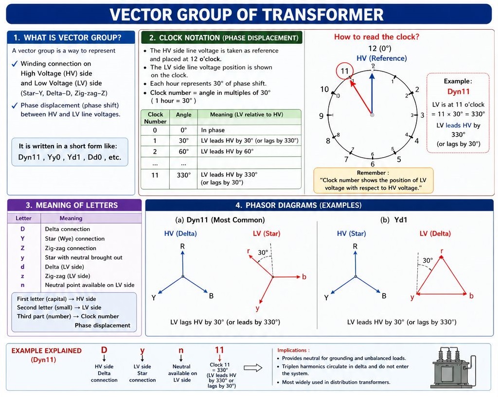
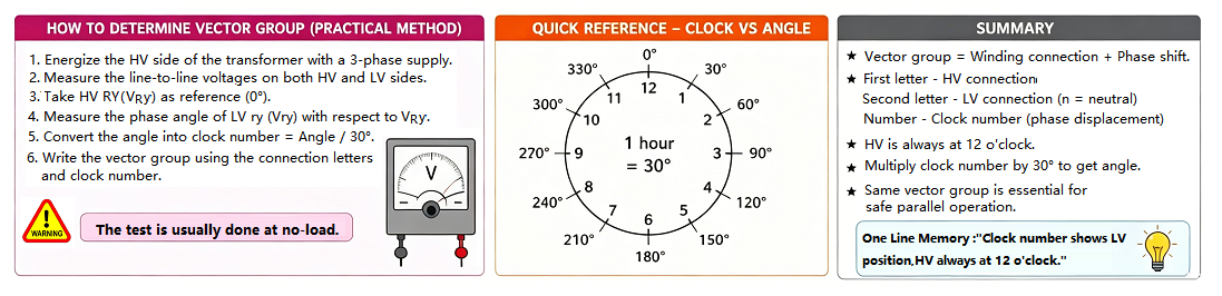
Transformer Vector Groups specify the connection types of the primary (high-voltage, HV) and secondary (low-voltage, LV) windings—such as Delta (D), Star (Y), or Zigzag (Z)—as well as the phase displacement between their respective voltages. This phase difference is conventionally represented using the "clock method," where the HV winding serves as the reference pointer fixed at 12 o'clock, and the position of the LV winding indicates the magnitude of the phase shift, with each hour mark representing 30° (e.g., 1 o'clock represents a 30° lag, 6 o'clock represents 180°, and 11 o'clock represents a 330° lag or 30° lead). For instance, in the widely used distribution transformer vector group Dyn11, "D" denotes a delta-connected HV side, "y" denotes a star-connected LV side, "n" indicates an accessible neutral terminal, and "11" signifies that the LV voltage leads the HV voltage by 30°. Other commonly applied vector groups include Yy0 (Star-Star) and Dd0 (Delta-Delta), both exhibiting 0° phase displacement, as well as Yd1 (Star-Delta), which features a 30° phase lag.
Why specify the vector group?

The Vector Group design of transformers is essential to ensure that transformers can operate correctly within different power systems and work effectively with other transformers or loads. Different vector groups have different phase relationships, and selecting the appropriate vector group is crucial for maintaining the stability, reliability, and efficiency of the power system. The main reasons include:
Characteristics of each Connection Group
1.Yy Connection Groups:
Yy0: Both the primary and secondary windings are connected in star. The corresponding line - to - line voltages are in - phase, with a phase difference of 0°. In the clock - notation method, when the primary - side line - voltage phasor is used as the minute hand pointing at 12 o'clock, the secondary - side line - voltage phasor also points at 12 o'clock.
Yy4: When the primary - side line - voltage phasor (as the minute hand) points at 12 o'clock, the secondary - side line - voltage phasor points at 4 o'clock. The secondary - side line - voltage lags behind the primary - side line - voltage by 120°.
Yy8: The secondary - side line - voltage lags behind the primary - side line - voltage by 240°. It is equivalent to the position where the minute hand is at 12 o'clock and the hour hand is at 8 o'clock in the clock - notation.
Yy6: Here, the secondary - side line - voltage lags behind the primary - side line - voltage by 180°. That is, the minute hand is at 12 o'clock and the hour hand is at 6 o'clock.
Yy10: The secondary - side line - voltage lags behind the primary - side line - voltage by 300°, corresponding to the 10 - o'clock position on the clock.
Yy2: The secondary - side line - voltage lags behind the primary - side line - voltage by 60°, similar to the situation where the minute hand is at 12 o'clock and the hour hand is at 2 o'clock.
Comprehensive transformer maintenance requires precision tools at every stage—from factory acceptance testing (FAT) and site commissioning to daily inspection. To thoroughly evaluate your transformer's core and windings, discover more about the [Kingrun JYT Series turns ratio testers] for ratio verification, and the [Kingrun JYR Series winding resistance testers] for field winding diagnostics.
2. Yd Connection Groups
Yd1: The primary side is connected in star and the secondary side is connected in delta. The secondary - side line - voltage lags behind the primary - side line - voltage by 30°. In the clock - notation, when the primary - side line - voltage phasor points at 12 o'clock, the secondary - side line - voltage phasor points at 1 o'clock.
Yd5: The secondary - side line - voltage lags behind the primary - side line - voltage by 150°, corresponding to the 5 - o'clock position on the clock.
Yd9: The secondary - side line - voltage lags behind the primary - side line - voltage by 270°, equivalent to the 9 - o'clock position on the clock.
Yd7: The secondary - side line - voltage lags behind the primary - side line - voltage by 210°, that is, the minute hand is at 12 o'clock and the hour hand is at 7 o'clock.
Yd11: The secondary - side line - voltage lags behind the primary - side line - voltage by 330° or, in other words, leads by 30°. It is a commonly used connection group, often used in lines where the low - voltage is higher than 0.4 kV.
Yd3: The secondary - side line - voltage lags behind the primary - side line - voltage by 90°, corresponding to the 3 - o'clock position on the clock.
3. Other Connection Groups:
Yyn0: Yyn0 (Star-Star Connection, 0° Phase Shift)
Both the high-voltage and low-voltage windings are connected in star (Y) configuration.The neutral point of the low-voltage side (yn) is usually grounded, allowing for a three-phase four-wire system, the phase shift is 0°, meaning the voltage on both sides remains in phase.Suitable for applications where the neutral grounding is essential, such as distribution transformers. However, it has poor unbalanced load handling and is susceptible to third harmonic currents, requiring proper grounding or compensation.
Yyn0 is suitable for balanced loads and is commonly used in small distribution transformers.
Dyn11: (Delta-Star Connection, -30° Phase Shift)
The high-voltage side is connected in delta (D) configuration, while the low-voltage side is connected in star (Y) configuration with a neutral point (yn),the low-voltage side voltage lags the high-voltage side by 30° (i.e., a -30° phase shift), offers better unbalanced load handling as the delta-connected high-voltage side provides a circulating path, reducing the impact of third harmonics.Commonly used in distribution systems requiring high power quality, such as industrial and commercial power supply.
Dyn11 is ideal for unbalanced loads and has better harmonic suppression, making it a popular choice in distribution systems
 Field Testing & Diagnostics Note: When transitioning from vector group verification to insulation health assessment, the winding configuration directly impacts your test setups. For instance, knowing whether a transformer is Delta (D) or Winding-Neutral (Yn) helps engineers properly configure a Tan Delta Tester to isolate leakage currents using UST or GST modes. Similarly, when deploying a partial discharge tester, understanding the vector group ensures correct sensor placement on the corresponding high-voltage bushings or neutral lines to accurately capture localized ionization signals.
1. Global Top 10 Transformer Manufacturers (2025)
2.Why most distribution transformers use Dyn11 connection?
3.Comparison of the Advantages and Disadvantages of Transformer Dd Yy Yd and Dy Configurations
4.What is the Difference between “Ratio” and “Turns Ratio” in a Transformer?
5.What are the main items of a transformer "Factory Acceptance Test(FAT)"?
6. How to correctly test the DC winding resistance of transformer?
7.5 Key Factors Affecting the Accuracy of Transformer Winding Resistance Testing
8.What are the Common Mistakes in Selecting Transformer DC winding resistance testers?
9.Why is it a Priority to Measure the Winding Resistance of the Transformer?
10.What is the Difference between Winding Resistance and Insulation Resistance and How to Test Them?


Kingrun Transformer Instrument Co.,Ltd.


