
Conductor resistance is one of the most important testing items in many wire and cable quality inspection projects. In the actual detection process, the deviation of the measurement result is often caused by neglecting certain factors.
1 Overview
The test method for DC resistance of wire and cable is as follows: Cut the sample of not less than 1 m from the cable to be tested as required, and remove the insulation, sheath or other covering of the outer surface of the test conductor to expose the conductor. Before the sample is connected to the measuring system, clean the conductor surface of the joint to remove the deposits and oil stains. After the oxide layer on the surface of the joint is removed as much as possible, fix the conductor sample on the special four-terminal fixture. After the four test ends of the bridge are reliably connected to both ends of the conductor, the DC power switch is closed, and the instrument starts to measure after preheating. Adjust the bridge balance. Read the bridge reading, record at least four significant digits, accurately measure the actual length of the tested conductor between the fixtures after turning off the test power, record the ambient temperature, and convert the measurement result to the resistance value of 1km conductor length at 20 °C as the final Report the value.
2. System error
In general, the conductor resistance of the samples we tested is much less than1 Ω/m. Usually, the double-arm bridge and the dedicated four-terminal measuring fixture are used, and the sample, standard resistance, galvanometer, varistor, ammeter, and connection are used. Test equipment such as wires, switches, thermometers, etc., combined into a measurement system for testing. It can be seen that the accuracy, verification and calibration of the testing equipment are the main causes of systematic errors. How to reduce system errors? We should periodically verify and calibrate the testing equipment to ensure that the accuracy of all equipment meets the testing needs. When using a double-arm bridge, the wire resistance between the standard resistance and the sample should be significantly less than the resistance of the standard resistance and the sample. Otherwise, appropriate methods should be used to compensate, such as wire compensation, so that the coil and lead resistance ratio is sufficiently balanced. The requirement for the fixture is that the distance between each potential contact and the corresponding current contact is not less than 1.5 times the circumference of the sample section.
3. Process error
Process error can also be called method error, which is the error caused by improper use of the method or measurement program error during the whole measurement process. In the standard, the detection of the conductor resistance is clearly defined.
A. Sampling. The preparation of the sample is very important, involving the surface treatment of the sample, the current introduction method, the type of the fixture, and the like. The basic technical route is to reduce the influence of contact resistance in the stranded conductor due to the condition of the single-wire surface, so that the distributed current in each single line is uniform to improve the measurement accuracy. The length of the intercepted sample should be no less than 1m, the distance between the fixtures is 1m, and the two clamps are 20cm, so we should generally sample from 1.4m to 1.5m. The sample insulation layer is removed and the conductor cannot be damaged. The specimen shall not be bent or measured during the measurement, because the length and cross-sectional area of the specimen are factors that affect the accuracy of the conductor resistance measurement. Before the sample is connected to the bridge, the surface of the conductor should be cleaned beforehand to remove surface contamination and oil stains and oxide layer on the surface. When measuring the resistance of large-section aluminum conductors, there are specific requirements in the standard: conductor cross-sectional area (95-185) m2, take 3m; 240m2 and above, take 5m, controversial conductor cross-sectional area 185m2 and below, take 5m , 240m2 and above, go 10m, and the current lead-in end should be crimped with aluminum crimping joint. The potential electrode can be knotted with a soft copper wire with a diameter of about 0.1m2 and tightly wound around the winding wire for 1-2 turns to prevent loosening.
B. Detection. The sample should be placed in the experimental environment for a certain period of time to ensure that the conductor temperature and the environment are balanced. The sample can also be immersed in a temperature controlled liquid bath for at least one hour. The measurement should be completed in a short period of time so that the temperature change before and after the test is not more than 1 °C. At the same time, the resistance value of the wire and cable can be estimated as accurately as possible, or the reference value of the conductor resistance corresponding to the standard model can be used as a preset value to reduce the measurement time, which can reduce the heat of the sample or the heat dissipation of the human body. The error caused by the increase in ambient temperature. In measuring small resistance (0.1Ω), we can use the current commutation method to read a positive reading and a reverse reading respectively, and take the arithmetic mean. The commutation here is not to exchange the two ends of the cable, but to exchange Current input terminal, cable connection does not move. In the case of meeting the sensitivity requirements of the test system, a smaller test current should be selected as much as possible, because large currents tend to cause the conductor to heat up rapidly, resulting in measurement errors.
4. Environmental error
The standard requirements for the external environment of conductor resistance measurement are also very strict. We should effectively control the measurement environment requirements within the range of ±1 °C within the range of the allowable fluctuations of the parameters specified by international standards. The temperature during the test shall be in the range of (15 °C - 25 °C). During the routine test, the temperature shall be within the range of (5 °C - 35 °C), and the air humidity shall not exceed 85% RH. The lower limit is not required. Therefore, when choosing a laboratory, you should first choose constant temperature and humidity. If you do not have this condition, you should consider a room with small air flow, relatively closed, and humidity should not be too large, avoiding heat radiation and air convection. The requirements for temperature control equipment must be high. It is recommended to use FM dual-temperature air conditioner. The accuracy of temperature measurement equipment should reach 0.1 °C. The temperature measuring equipment used must be periodically verified or calibrated, and the temperature measuring equipment should be placed within a range of not less than 1 m from the ground, no less than 10 cm from the wall, no more than 1 m from the specimen, and approximately the same height as the specimen. . The sample should be placed in the laboratory for not less than 16 hours to ensure that the temperature of the sample is balanced with the temperature of the test environment, and the measurement error caused by the change of the ambient temperature should be avoided as much as possible.
5. Human error
The tester of the conductor resistance test shall pass the relevant standard training, pass the examination, and hold the inspector's certificate to test. The inspectors should have a deep understanding of the relevant standards, know the factors that will affect the measurement results during the experiment, pay attention to the improvement of the inspection skills, and be proficient in various methods of measuring the conductor resistance. Careful and careful reading, try to avoid artificial error. If necessary, we can take a multi-person comparison method to verify the measured value of the conductor resistance. The resistance measurement value shall be the final reported value according to the resistance value of 1km conductor length which shall be converted to 20 °C according to the IEC60051 standard. In the conversion process, the value correction and the effective number retention shall be correctly performed according to the standard requirements.
6. Summary
Any measurement result, due to the limitation of operating conditions, will produce errors. This paper analyzes the cause of the error in the DC resistance measurement of the conductor and proposes a corresponding solution. The purpose is to effectively control the above error and make the measurement result. Closer to the true value.
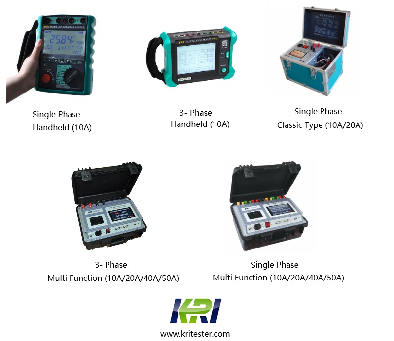
Kingrun transformer winding resistance tester has the excellent and stable performance,rapid testing, small size, easy carrying, high measurement accuracy, automatic power-saving and other characteristics. It is an ideal instrument for measuring transformer winding resistance and DC winding resistance of high-power inductors.
Related Articles:
The Most Complete Transformer Vector Group Collection with Winding Connection Diagrams
How Important is Transformer DC Winding Resistance?
Top 6 Transformer winding resistance testers Worldwide (Including Prices)
How should Winding Resistance be Tested Differently on CT and PT?
What is the Difference between DC Resistance and Insulation Resistance and How to Test Them?
8 Tips to Improve the Accuracy of DC Resistance Measurement
Why is the Tested Winding Resistance Always Inaccurate? You May Have Overlooked These 6 Key Points
Kingrun Series DC winding resistance testers

Kingrun Transformer Instrument Co.,Ltd.


