
Among various transformer or motor parameters, DC resistance and insulation resistance are two of the most critical ones, although their names sound similar, they have fundamentally different meanings. Simply put, DC resistance measures how easily current flows within a conductor, reflecting the integrity of the winding; insulation resistance measures how well current is prevented from leaking through insulation, reflecting its quality.
Insulation Resistance
Insulation resistance represents the ability of transformer insulating materials (such as oil, paperboard, or varnish) to resist leakage current. It is usually measured with a high-voltage DC bridge or an insulation resistance tester (megohmmeter). It reflects the insulation performance between windings, and between the winding and the core or enclosure. The measured value indicates the degree of moisture absorption, aging, or contamination of the insulation. A qualified insulation resistance value is generally very high—typically in the megohm (MΩ) to gigaohm (GΩ) range—and decreases significantly with rising temperature and humidity.
The purpose of the DC resistance testing
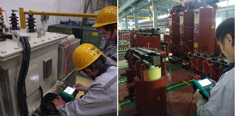
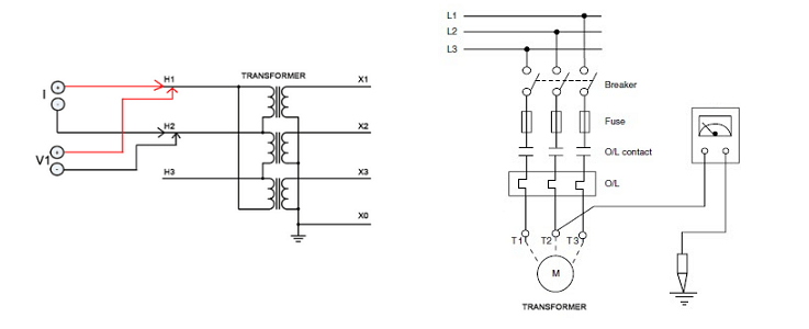
The purpose of the DC resistance testing is to check the quality of the windings or windings of the transformers or motors and the integrity of the circuit to find the wire breakage, joint welding, poor contact, and inter-turn short circuit caused by mechanical stress caused by vibration during manufacturing or operation. And other defects. In addition, when the temperature rise test is performed on the generator and the transformer, the temperature value under the corresponding load is also converted according to the DC resistance value under different loads.
The purpose of the insulating resistance testing
Measuring the insulation resistance of the transformers and motors is the easiest way to check the insulation state. The megohmmeter is commonly used to measure the insulation resistance. Since the selected megohmmeter voltage is lower than the working voltage of the test object, this test is a non-destructive test, and the operation is safe and simple. From the measured values of the insulation resistance, it is found that the foreign matter which is currently affecting the insulation of the electrical equipment, the local or overall insulation of the insulation is wet and dirty, the insulation oil is seriously deteriorated, the insulation breakdown and severe heat aging are defects.
Other Related Articles:
Why Does the Contact Resistance Testing Need 100A or Higher?
Hazards and Treatment of Excessive Contact Resistance of Circuit Breakers or HV Switches
How to measure the contact resistance without changing the circuit?
How to Correctly Test the Contact Resistance of HV Switchgear or Circuit Breaker?
Why Does Excessive Contact Resistance Occur In Electrical Secondary Circuits?
What is the Testing Checklist for 110kV/220kV Substation Acceptance and Maintenance Testing?
More Transformer Testers from Kingrun


Kingrun Transformer Instrument Co.,Ltd.


