Partial Discharge (PD) testing is an essential method for evaluating and monitoring the insulation condition of GIS high-voltage switchgear and transformers. The main reasons and significance of PD testing include the following:
1.Early Defect Detection and Warning
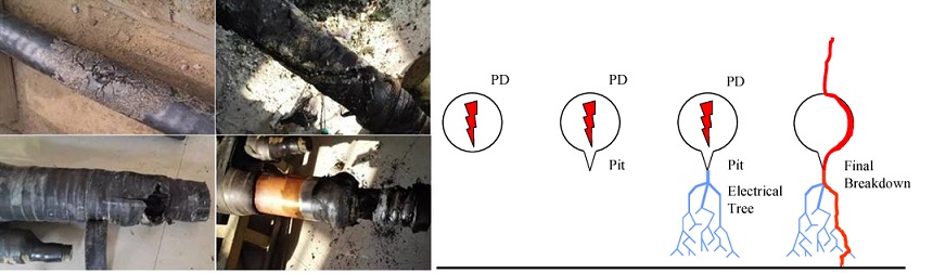
Partial discharge is a localized weak discharge phenomenon within the insulation system, often caused by the presence of micro-bubbles, cracks, impurities, aging, or manufacturing defects. PD testing can detect these hidden issues at an early stage, preventing the long-term degradation of the insulation system and stopping minor defects from evolving into major failures.
2.Ensuring Insulation Performance
GIS high-voltage switchgear and transformers operate under high voltage, complex environments, and gas insulation conditions. If partial discharge is not controlled, it can lead to localized deterioration of insulation materials, accelerating insulation aging and even causing insulation breakdown. Regular PD testing helps assess the health of insulation materials, ensuring stable insulation performance and operational safety.
3.Preventive Maintenance and Lifespan Management
By monitoring partial discharge signals, operators can evaluate the condition of the equipment and schedule timely maintenance or replacement, achieving preventive maintenance. This not only prevents unexpected failures but also extends the service life of the equipment, ensuring the long-term stable operation of the power system.
4.Quality Control and Process Optimization
Conducting PD testing during the manufacturing and installation stages helps identify defects in design, production, or installation processes. Timely feedback and corrections improve product quality and overall process standards, reducing operational risks in the later stages.
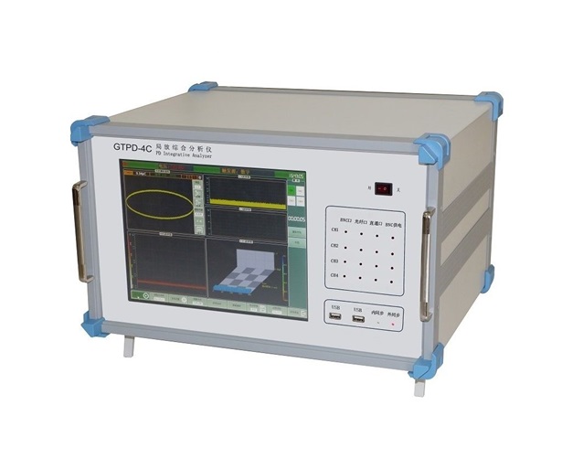
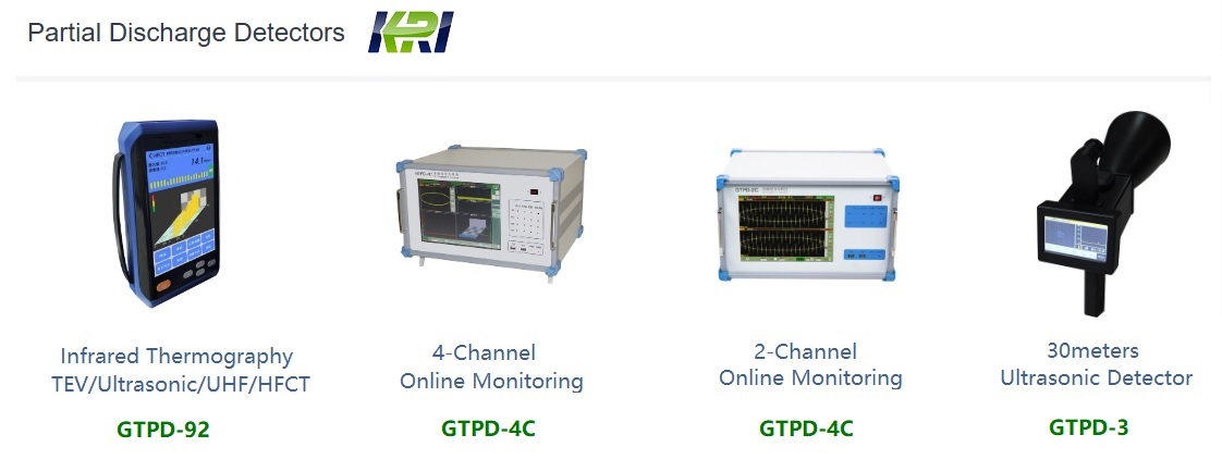
GTPD-4C partial discharge comprehensive detector is the new generation of digital PD measurement and analysis instrument, it has a strong ability of comprehensive analysis of partial discharge and detection of partial discharge in small signal and strong interference environment. With different accessories, it can measure and locate the partial discharge in any high voltage electrical equipment. It can realize testing the transformer partial discharge by applying the voltage on the three phases simultaneously.


Functions and Feature:
1. Multi signal channel, desktop, TFT liquid crystal display, reliable system, low failure rate, strong anti- interference ability.
2. It integrates functions of measurement, diagnosis, location and on-line monitoring.
3. The location of fault position can be achieved by electro-acoustic and acoustic-sound.
4. According to the testing process, the test report can be generated automatically and the report can be read and printed.
5. The replay function can restore the saved data file to the waveform displayed on the screen.
6. Four channels electrical signal and four channels optical signal input port can simultaneously realize the measurement and analysis of multi-channel partial discharge signal.

GTPD-4C PD Tester Specification
Channels
Independent 4 one for external
Nonlinear error of this range
5%
Sampling
frequency
1M, 5M, 10M (optional)
Measuring range
0.1pC~1000nC
Sampling
accuracy
12bit
Sensitivity
0.1pC
Measuring range
×1, ×10, ×100,
×1000, ×10000,
×100000
Capacitance range of specimen
6pF~250µP
Measuring
bandwidth
10kHz~1MHz
(3dB Bandwidth)
External synchronous
frequency input range
30Hz~400Hz
Digital filtering
10kHz~1MHz
(Arbitrary choice)
External synchronous
voltage input range
10V~400V
Programmable filter segment
Low frequency:
Power supply
AC220V, Frequency: 50Hz (customized)
10kHz, 20kHz,
40kHz, 80kHz OFF(10kHz)
High Frequency:
100kHz, 200kHz,
300kHz, 400kHz 800kHz,OFF(1MHz)
Display
Display
screen
12 inch TFT true color
touch LCD screen
resolution
1024×768
Interface
USB, Power interface, optical signal interface,
electrical signal interface, RJ45 internet interface, grounding button
Common description
Operation
system
Windows XP
CPU
1.6GHz
Size
474×288×370mm
Memory
2.0GB
Weight
15.8kg
Hard disc
128GB Solid state
hard disk
GTPD-4C PD Tester Application


Infrared Thermography (IRT) and Partial Discharge (PD) testing are two widely adopted condition monitoring techniques in modern power systems, each with distinct applications and technical strengths. IRT detects surface temperature anomalies to identify potential faults caused by increased electrical resistance, such as loose connections, overloads, or deteriorated contacts. Based on passive thermal radiation measurement, IRT is simple to operate, allows for non-intrusive and live inspections, and is particularly effective for components like switchgear, busbars, and cable terminations. However, it has notable limitations: it can only detect faults that produce significant heat and cannot identify early-stage insulation degradation or internal defects. The results are also influenced by ambient temperature, surface emissivity settings, and operator experience. In contrast, PD testing detects small electrical discharges occurring within or on the surface of insulation systems. These discharges often indicate the onset of insulation breakdown, such as voids, cracks, surface contamination, or moisture ingress, allowing for much earlier detection of critical insulation failures.
In summary, IRT is well-suited for identifying resistive faults and surface heating, while PD testing is more effective at detecting internal insulation degradation at an early stage. Integrating both methods enables a comprehensive asset monitoring strategy, combining surface thermal detection with internal dielectric diagnostics. Industry standards recommend joint application, and the reliability of the results depends heavily on the competency of the operators. Certified training (e.g., FLIR Level I/II for thermography or PD specialist training from EA Technology) is strongly recommended. By selecting the appropriate method based on asset type, voltage level, and environmental conditions, utilities and asset managers can significantly improve system reliability and reduce the risk of unplanned outages and catastrophic failures.
Kingrun Transformer Instrument Co.,Ltd.


More Transformer Testers from Kingrun