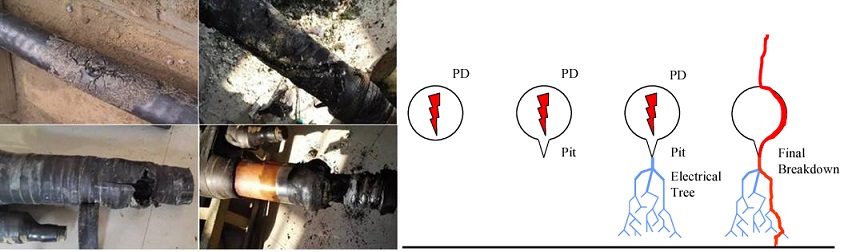
Partial discharge(PD) is a pulsed discharge that produces a series of physical phenomena and chemical changes such as light, sound, electrical and mechanical vibrations in and around electrical equipment. When insulation defects occur in high-voltage electrical equipment, partial discharge signals will be generated. Through the detection and analysis of these signals, it can be judged whether there are hidden dangers of insulation inside the high-voltage electrical equipment, and the further expansion of potential accidents can be prevented. So regular PD testing is critical as part of a condition-based management (CBM) regime. This enables operators to obtain baseline PD readings to assess insulation quality, locate PD activity and determine maintenance goals
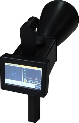
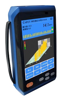
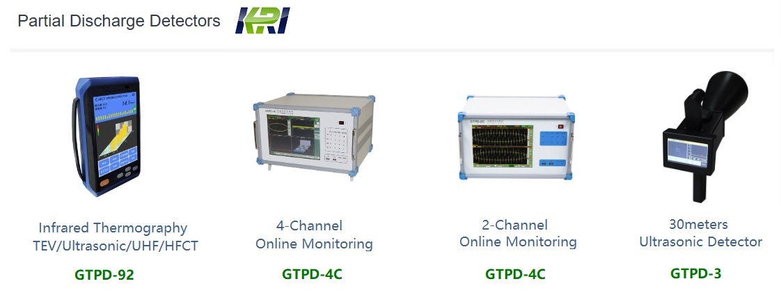
The partial discharge detector adopts a brand-new design and uses the currently popular Android system, which is easier to operate and use. In addition, it integrates 5 million pixel cameras to take pictures to facilitate inspection records; RFID is conducive to expanding the application of the Internet of things; internal integration discharge type library is provided to facilitate the comparison and verification of discharge conditions.
 GTPD-92")

|
Host parameters |
|
|
Detectable channels |
4 Channels 1 TEV 1 US 1 UHF(Wireless, optional) 1 HFCT(Wireless, optional) |
|
Sampling accuracy |
12bit |
|
synchronous mode |
Internal synchronization, external synchronization, and photosynchronization |
|
TEV |
|
|
Detecting bandwidth |
3M-100MHz |
|
Detecting range |
0~60dB |
|
Detecting deviation |
±2dB |
|
resolution |
1dB |
|
Max.number of pulses per cycle |
720 |
|
Mini. Pulse frequency |
10Hz |
|
Output interface |
Standard SMA connection host |
|
Non-contact US |
|
|
Center frequency |
40kHz |
|
Resolution |
0.1uV |
|
Accuracy |
±0.1uV |
|
Detecting range |
0.5uV~1mV |
|
Output interface |
Standard SMA connection host |
|
Contact US |
|
|
Center frequency |
20kHz~300kHz |
|
Resolution |
50 Ω |
|
Accuracy |
0.1mV |
|
Detecting range |
0.1mV~1V |
|
Output interface |
Standard SMA connection host |
|
UHF(optional) |
|
|
Detecting bandwidth |
300MHz~1.5GHz |
|
Output mode |
BNC interface-Signal conditioning unit, wireless connection to the host |
|
Receive mode |
Antenna receive |
|
Transmission mode |
Coaxial cable |
|
Detecting sensitivity |
≤60dBm |
|
HFCT(optional) |
|
|
Detecting bandwidth |
1M-30MHz |
|
Transfer impedance |
>5mV/mA (10MHz ) |
|
Output impedance |
50 Ω |
|
Detecting range |
-20~80dB |
|
Detecting deviation |
±1dB |
|
Accuracy |
1dB |
|
Output interface |
BNC Interface-Signal conditioning unit, wireless connection to the host |
|
Hardware |
|
|
Display screen |
A 5.0-inch TFT True color LCD screen |
|
Resolution |
800×480 |
|
Operation mode |
Touch / button |
|
Storage |
TF Card |
|
Sound interface |
3.5 mm Stereo headphone jack |
|
Power |
DC-12V/2A DC Power |
|
Extended function |
USB-Type/500Mega pixel camera/RFID/Wi-Fi/Bluetooth |
|
Power |
|
|
Internal Power |
battery powered(4800mAH 7.4V) |
|
Working time |
About 7 hours, and the filling time is about 3 hours |
|
Dimension |
|
|
L×W×H |
235 mm×133 mm×48 mm |
|
Weight |
0.85 kg |
|
Environment |
|
|
Use ambient temperature |
-20℃~50℃ |
|
Storage environment temperature |
-40℃~70℃ |
|
Humidity |
10%-90%(Non-condensation) |
|
Height above sea level |
≤3000 m |
 GTPD-92")
 GTPD-92")
 GTPD-92")
 GTPD-92")
 GTPD-92 on site")
 GTPD-92")
Infrared Thermography (IRT) and Partial Discharge (PD) testing are two widely adopted condition monitoring techniques in modern power systems, each with distinct applications and technical strengths. IRT detects surface temperature anomalies to identify potential faults caused by increased electrical resistance, such as loose connections, overloads, or deteriorated contacts. Based on passive thermal radiation measurement, IRT is simple to operate, allows for non-intrusive and live inspections, and is particularly effective for components like switchgear, busbars, and cable terminations. However, it has notable limitations: it can only detect faults that produce significant heat and cannot identify early-stage insulation degradation or internal defects. The results are also influenced by ambient temperature, surface emissivity settings, and operator experience. In contrast, PD testing detects small electrical discharges occurring within or on the surface of insulation systems. These discharges often indicate the onset of insulation breakdown, such as voids, cracks, surface contamination, or moisture ingress, allowing for much earlier detection of critical insulation failures.

In summary, IRT is well-suited for identifying resistive faults and surface heating, while PD testing is more effective at detecting internal insulation degradation at an early stage. Integrating both methods enables a comprehensive asset monitoring strategy, combining surface thermal detection with internal dielectric diagnostics. Industry standards recommend joint application, and the reliability of the results depends heavily on the competency of the operators. Certified training (e.g., FLIR Level I/II for thermography or PD specialist training from EA Technology) is strongly recommended. By selecting the appropriate method based on asset type, voltage level, and environmental conditions, utilities and asset managers can significantly improve system reliability and reduce the risk of unplanned outages and catastrophic failures.
Kingrun Transformer Instrument Co.,Ltd.


More Transformer Testers from Kingrun


turn ratio tester, transformer test instrument, winding resistance tester,