Test principle and precautions for using large grid earthing resistance tester
I、Overview
Recent years, many substations due to lightning strikes formed expansion accidents, most of them are related to the ground grid grounding resistance is unqualified, the grounding grid plays the role of working grounding and protective grounding, when the grounding resistance is too large: When a ground fault occurs, the neutral point voltage offset increases, which may make the sound phase and neutral point voltage too high, exceeding the level of insulation requirements and causing equipment damage. In the lightning strike or lightning wave attack, due to the large current, a high residual voltage will be generated, so that the nearby equipment is threatened by counterattack, and the lightning resistance level of the live conductor of the grounding network itself protection equipment (overhead transmission lines and substation electrical equipment) is reduced, and the equipment is damaged if it does not meet the design requirements. At the same time, whether the grounding resistance of the grounding system is qualified is directly related to the personal safety of substation operators and substation maintenance personnel; However, due to the corrosive effect of the soil on the grounding device, with the extension of the operating time, the grounding device has corroded, which affects the safe operation of the substation; Therefore, the regular monitoring of the grounding resistance of the ground grid must be greatly strengthened; The measurement of the grounding resistance of the ground grid of the substation during operation is due to the interference of the current flowing into the ground grid of the system and the interference between the test leads, which causes a large error in the test results. In particular, the grounding resistance of large grounding grid is very small (generally below 0.5Ω), even slight interference will have a great impact on the test results; if the grounding resistance test of the ground grid is not accurate, not only damage the equipment, but also cause unnecessary losses such as ground grid faulty transformation, combined with my research on grounding resistance test methods of grounding grid, it is summarized as follows:
II、Grounding resistance test principle and method test the grounding impedance of the grounding device when the current pole should be arranged as far as possible, usually the distance dcG between the current pole and the edge of the grounding device under test should be 4~5 times of the length D of the large diagonal of the grounding device under test (parallel wiring method), in the area of uniform soil resistivity can be taken 2 times and above (triangle wiring method), the length of the voltage lead is 0.618 times the length of the current lead (flat wiring method) or equal to the current line (triangle wiring method).
1. The grounding impedance of the potential drop test grounding device is arranged according to Figure 1 and meets the requirements of the layout of the test circuit.
G—grounding device under test; C—current pole; P—potential electrode; D—the length of the large diagonal of the grounding device under test; dCG—the distance between the current electrode and the edge of the grounding device under test; x—the distance between the potential electrode and the edge of the grounding device under test; d—Test distance interval; The current I flowing through the grounding device G and the current pole C changes the ground potential, and the potential pole P moves outward from the edge of G in the direction of 30 ° ~ 45 ° with the current loop, and the potential difference U between ciP and G is tested every interval d (50m or 100m or 200m), and the change curve of U and x is drawn. The flat place of the curve is the potential zero point, and the potential between the curve point is the potential increase U of the grounding device under the test current, and the grounding impedance of the grounding device is:
Z=Um/I If it is really difficult to put the potential test line and the current line at an angle, it can be placed in the same path, but keep the distance as far as possible.
If the potential will be difficult to determine the flat point of the curve, it may be affected by the grounding device under test or the current pole C, and the extension of the current loop is considered; Or the underground situation is complex, consider other methods to test and verify.
2. Current-voltmeter three-pole method a) straight-line method The current line and potential line in the same direction (same path) defense is called the straight-line method in the tripolar method, schematic diagram 2; dcG meets the requirements of the layout of the test loop, dPG is usually (0.5~0.6) dcG. The potential pole P should be moved three times in the direction of the connection between the grounding device G and the current pole C under test, and the distance of each time is about 5% of dcG, when the error of the result of the three tests is within 5%.
Large grounding devices are generally not suitable for straight-line testing. If conditions are limited and must be used, care should be taken to keep the current line and potential line as far away as possible to reduce the influence of mutual inductance coupling on the test results.
G—grounding device under test; C—current pole; P—potential electrode; D—large diagonal length
dCG—distance between the current pole and the edge of the grounding device under test; dPG—the distance between the potential electrode and the edge of the grounding device under test;
b) Angle method
As long as conditions permit, the test of ground impedance of large grounding devices adopts the method of current-potential line angle arrangement. dcG meets the requirements of the layout of the test circuit, generally 4D~5D, and the ultra-large grounding device is as far as possible; dPG is similar in length to dcG. The ground impedance can be corrected using equation (2).
(2) where
θ --- angle between current line and potential line;
Z''--- Test value for ground impedance.
If the soil resistivity is uniform, isosceles triangle wiring with dc G and dpG equal can be used, in which case θ is about 30°, dcG=dpG=2D grounding correction Equation 2.
3. Grounding resistance tester method.
Figure 3 is the wiring method of the grounding resistance tester to test the grounding resistance of the grounding grid; The test principle, wiring, and requirements are similar to the tripolar method.
1. The E pole must be short-connected with P1 when using the triode method, but the ground resistance of the local grid is very small, and when the ground resistance of the local grid is small (≤ 0.5Ω), in order to improve the measurement accuracy and reduce the influence of the instrument and the ground grid measurement lead resistance and contact resistance on the measurement results, the E.P short circuit piece can be unlocked; reduce the error caused by the contact resistance, and the separate lead needs to be connected to the ground network test point.
Note:
1, E - connected to the surveyed ground network;
2, P1 - connected to the measured ground network; 3. P2 - connected to the measured voltage line (its length is taken
as 0.618 times the length of the current line); 4. C - connected to the
measurement current line (its length is taken from 4~5 times the diagonal length of the ground network);
III、Test precautions and significance The characteristic parameters of the large grid earthing resistance testerare mostly closely related to the moisture degree of the soil, so the condition assessment and acceptance test of the grounding device should be carried out as much as possible in the dry season and when the soil is not frozen, and should not be carried out immediately after thunder, rain, snow or rain and snow. Through actual measurement, it provides us with a stable basis for rectification. For the grounding condition of the grounding network of the substation, a rectification and optimization plan is proposed to make the grounding resistance of the grounding grid meet the requirements, so as to effectively prevent the step voltage caused by the insulation damage of the equipment from causing personal injury or further damage to the equipment. It plays a role in ensuring the safe operation of electrical equipment and creating a safe and stable working environment for substation staff.
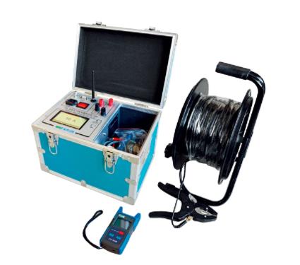
JYD Grounding Down Wire Continuity Tester (large grid earthing resistance tester) (10A)
Using advanced power supply technology, it is a highly automated portable tester used to measure the on-resistance value between the grounding down-conductors of various power equipment in the substation.