Winding resistance measurement (WRM) is a critical diagnostic tool for assessing winding integrity and connection reliability. Selecting the appropriate tester is fundamental to ensuring data accuracy and operational safety. In diverse engineering environments—governed by standards such as IEC 60076, ANSI/IEEE C57.12.90, and UL 5085—differences in transformer architecture and parameters often lead to selection errors. These errors compromise measurement precision and equipment safety.
The following sections analyze five critical selection pitfalls and provide technical guidelines for selecting the optimal DC resistance tester.
A common misconception is that higher test currents always yield higher precision and faster stabilization. In practice, excessive current can cause localized heating and thermal drift in the windings, while insufficient current fails to overcome the inductive time constant of large power transformers.
Case Study: Thermal Drift in UL Class 2 Transformers
An operator used a 40A tester on a 100VA UL Class 2 distribution transformer (ANSI 70/UL 50853). The high-voltage winding resistance was approximately 25Ω. At 40A, the low-voltage winding temperature rose to 60°C within 5 minutes, causing a resistance drift exceeding ±0.8% (violating the ±0.2% precision requirement). Furthermore, the tester's 40A rating was a peak value, not a continuous duty cycle, leading to a thermal shutdown.
Engineering Resolution: Switching to a 10A tester with continuous current output and magnetic circuit saturation (magnetic assistance) technology stabilized the temperature within ±5°C of ambient, reducing fluctuations to within ±0.3%.
Selection Criterion: Calculate the required continuous current based on winding resistance (R) and MVA rating. For high-impedance windings, prioritize testers with stable, lower current ranges and magnetic assistance.
Factory-stated accuracy is often measured in controlled laboratory environments. In high-voltage substations, Electromagnetic Interference (EMI) from adjacent energized equipment can cause data instability. Without third-party calibration and robust shielding, the validity of the test results is compromised.
Case Study: EMI Distortion in IEC 60076 Main Transformers
During a 220kV/315MVA (YN/d11) transformer test, a low-cost tester with a nominal ±0.1% accuracy showed ±1.2% fluctuations due to electromagnetic noise from a nearby switchgear. The data deviated from factory test reports by >3%. Replacing it with a CE-certified tester featuring dual-layer shielding and active noise suppression reduced fluctuations to ≤±0.3%, aligning with ANSI C57.12.91 requirements.
Selection Criterion: Ensure the instrument holds a third-party calibration certificate covering the full measurement range. Verify the presence of active EMI filters and shielded enclosures.

Test lead quality, input voltage flexibility, and data management are often treated as secondary but are vital for field reliability.
Case Study: Lead Resistance in NEMA 4X Transformers
A 1600kVA NEMA 4X distribution transformer (DOE 2016 compliant) was tested using standard 2.5 mm2 leads. High contact resistance and oxidation in a high-humidity environment caused a 0.6% upward bias in readings. Additionally, the tester failed to start when the site voltage sagged to 180V.
Engineering Resolution: Utilizing silver-plated copper Kelvin clips with ≥4 mm2 cross-section leads and a wide-range power supply (160V–260V) eliminated the measurement bias and power-on issues.
Selection Criterion: Specify ≥4 mm2 silver-plated copper leads (minimum 3m length). Require wide-input voltage capability and data storage for ≥1000 records with USB/Bluetooth export.
Complex winding configurations (Delta, Zig-zag, YN) and the presence of On-Load Tap Changers (OLTC) require specific tester functionalities. Standard testers may result in excessive downtime or failure to detect contact defects.
Case Study: Efficiency Loss in 230kV ANSI Power Transformers
Testing a 500MVA transformer with an OLTC using a single-channel tester took 8 hours due to manual lead swapping. This process also led to a false-positive diagnosis of a tap changer fault. Upgrading to an 8-terminal/6-winding simultaneous measurement system with integrated OLTC verification and automatic core demagnetization reduced the test time to under 2 hours and accurately identified a high-resistance contact in the tap changer.
Selection Criterion: For power transformers, select testers supporting multi-channel simultaneous measurement, OLTC transition testing, and automatic demagnetization.

Low-cost "white-label" instruments often lack CE, UL, or ISO 9001 certifications. In international projects, the lack of local technical support can lead to significant project delays.
Case Study: Service Failure in an IEC Project
A non-certified tester failed during a 500kVA transformer commissioning in Africa. Due to a lack of local service infrastructure, the unit had to be shipped back to the manufacturer, causing a 45-day delay and over $15,000 in liquidated damages and rental costs.
Selection Criterion: Prioritize reputable brands with international certifications and documented After-Sales Service Level Agreements (SLAs), including 24-hour technical support.
Technical Compatibility: Align current output and measurement algorithms with the specific transformer standard (ANSI/IEC), capacity, and winding resistance.
Regulatory Compliance: Ensure all equipment is traceable to national or international standards (NIST/PTB) via third-party calibration.
Field Resilience: Prioritize EMI immunity, wide-range power inputs, and high-durability accessories (Kelvin clips and leads).
Lifecycle Support: Evaluate the manufacturer’s ability to provide field calibration, software updates, and global technical assistance.
Kingrun Transformer Instrument Co.,Ltd.


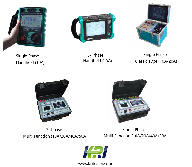
Kingrun Series DC winding resistance testers