
The DC resistance of the transformer or motor refers to the DC resistance value of each phase winding. The purpose of measuring the DC resistance is to check whether there is an inter-turn short circuit inside the three-phase winding. Because if a phase-to-phase short circuit occurs inside the transformer, the short-circuit current value is very large, it is easy to burn the transformer or motor, the phenomenon of the fault is also obvious, and the appearance is easy to judge; however, if a short circuit occurs between the winding turns of one of the phases, the short-circuit current If the value is small, the gas protection of the transformer will trip, but it is difficult to see whether the transformer itself is faulty from the appearance of the transformer.
By measuring the DC resistance of each phase, it is easy to judge whether an inter-turn short circuit occurs internally through the comparison of the three-phase resistance values: the resistance value is very different, and the possibility of inter-turn short circuit fault is very large; if it is basically similar, this can be ruled out.
Because according to the structure of the transformer, the windings are almost insulated by the insulating medium of the insulated wire itself. If there is a defect in the insulation treatment, and the transformer has a large load, the weak insulation is likely to cause a short circuit between turns. Therefore, the purpose of measuring the DC resistance is to judge whether the transformer is short-circuited between turns, which is convenient for troubleshooting.
The purpose of measuring the DC winding resistance of the transformer windings or motor winding is to check the welding quality of the winding joints and whether the windings have short circuits between the windings; whether the contact positions of the voltage tap switches are good and whether the actual positions of the taps match; whether there is a break in the lead wires or not. Stranded wires and windings have broken stocks. When the transformer is overhauled or after changing the tap position, or after the outlet fault is short-circuited, the DC winding resistance of the winding together with the bushing needs to be measured.
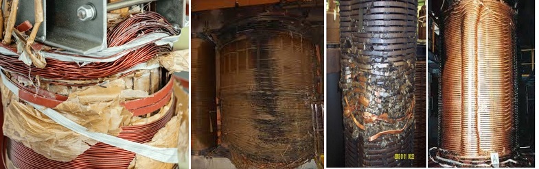
6 Cases of Transformer Short Circuit Discovered by DC Resistance Test
Therefore, the winding short circuit of the transformer is a common fault, which will lead to problems such as current instability, transformer heating, and equipment damage. It is a common method to detect short circuits in transformer windings with a DC resistance instrument. The following is a practical case of using a DC resistance instrument to find a short circuit in a defective winding of a transformer:
Case 1: A 16000kVA, 6.3kV transformer, the three-phase unbalance rate of the low-voltage winding before treatment is 2.82%, the three-phase separation of the secondary winding, and the DC resistance is measured separately, B is 7.8% larger than A-phase and C-phase, the inspection found The lead wire of the B phase winding is poorly welded, one of the three flat copper wires is broken, and the white cloth tape wrapped with 7-8 layers is burned black. After reprocessing, the DC resistance is normal, and the three-phase unbalance rate drops to 0.005%.
Case 2: 31500kV, 10kV transformers, factory DC resistance unbalance rate is 3.6%, 2.5% before operation, 2.7% during pre-test. After a sudden short circuit, the unbalance rate was measured to be 3%. After 5 times of shock closing, the measured DC resistance unbalance rate is 42.8%. Upon inspection it was found that:
1) There was a short circuit between the second turns at the lower outlet of one low-voltage A-phase coil, and the insulation and separators were burned.
2) The axial and radial displacement of the short-circuit winding is about 20mm.
Case 3: A 120,000kVA, 220kV transformer has been in operation for 25 years. In 1991, it was found that the DC resistance was abnormal, and the unbalance rate reached 4.2%.
Measuring the contact resistance of the connector at the outlet end of the low-voltage winding, it was found that the B terminal and the C terminal have increased from 10uΩ to 300uΩ. The inspection found that the nuts and screws on the two joints of the low-voltage winding B and C lead wires were melted. Nuts and washers have burn marks and melting points.
Case 4: For 2000kVA, 63kV transformers, the DC resistance test results show that at the No. 9 tap position, the DC resistance deviation is 9.8%. The inspection found that the spring pressure of the on-load tap changer was insufficient, the screw was not tightened, and the mechanical switch of the switch was not in place. The polarity switch is a virtual contact with the common point K, and the contact has arc burn marks, and the DC resistance is balanced after treatment.
Case 5: A SFPSL-120000/220 transformer has been in operation for 18 years, and all previous test results including DC resistance are normal. After a surface flashover accident occurred on the 110kV side CT, the transformer tripped and caught fire. Analyzing the test results of DC resistance, it is found that the unbalance rate of each phase resistance meets the requirements of the full specification. In the test results in the first half of the accident, although the three-phase DC resistance on the medium voltage side was balanced, it was different from previous years at the same temperature. Compared with the average test value, each phase increased by about 8.15% (both high and low voltages did not exceed 2%), indicating that the neutral point bushing on the medium voltage side had poor contact defects, but no analysis was made after the test, and there was no current in normal operation. Passed, the chromatogram cannot reflect until an accident occurs.
Case 6: A 120MVA, 220kV transformer suddenly tripped during light and heavy power protection and differential protection, oil injection, and oil chromatography analysis as arc discharge, which involved solid insulation characteristics. The three-phase DC resistance of the high-voltage winding is unbalanced, and A is about 12% larger than the two-phase B and C. Lifted the transformer case and found that the phase A high voltage I coil was short circuited between the turns of the 5th section from top to bottom, and it was blown up. Why does the DC resistance of the winding only increase by 12% after the inter-turn short circuit of the winding is blown? This is determined by the winding structure. The winding of the transformer is a high-low-high structure, that is, the outermost layer is a high-voltage I coil, the middle is a low-voltage coil, and the innermost layer is a high-voltage II coil. High voltage I and high voltage II are connected in series to form a high voltage winding. together, then in series with the High Voltage II.
The number of turns of A1O1 or A2O2 is equal, accounting for about 1/4 of the number of turns of AO1.
Assume that the resistance of each segment has the following relationship:
RAO1=RAO2=4RA2O2=2RO1O=4RAA1/3
Under normal circumstances:
R(HV)=RO1O+RAO1/2=RAO1
After A1O1 accident fuse
R (HV) = RO1O+RAA1/2+RA2O2
That is, after the accident, the resistance of the high-voltage winding was about 12.5% larger than that under normal conditions.
In the same way, it can be seen that if a high-voltage I short circuit occurs between turns and the wire is blown, the resistance of the high-voltage winding will increase by about 27%. For ordinary high-low structure transformers, the inter-turn short circuit is blown in the high-voltage area, and the resistance of the high-voltage winding increases by about 80%. According to the above experience and calculation, according to the resistance change, the fault zone can be roughly judged. Of course, there are very few cases where the wires are not completely blown after the inter-turn short circuit, and the DC resistance of the coil does not change significantly.
Through the test results, the power engineer confirmed the short circuit problem of the transformer winding and repaired it in time. In the end, the transformer was able to resume normal operation, ensuring the stable power supply of the power system.
The measurement method is as follows:
(1) Current, voltage meter method. Also known as voltage drop method, the principle is to pass a direct current in the measured resistance, measure the voltage drop on the resistance, according to Ohm's law to calculate the measured resistance value. Since the internal resistance of the ammeter and voltmeter will affect the measurement results, the way they are connected to the measurement circuit should be carefully considered.
(2) Balanced bridge method. It is a method to measure the DC winding resistance using the principle of bridge balance. The commonly used balanced bridge has two kinds of single-arm and double-arm bridges. When measuring the DC winding resistance of the transformer, it should be performed after the transformer is powered off and the high voltage lead removed. For large-scale large-capacity power transformers, the charging time constant τ of the series circuit is very large, making each measurement takes a long time to wait for the current and voltmeter indication to be stable, so the working efficiency is very low, and special instruments (such as constant current) are often used. Power supply instead of the power supply in the test, which can greatly reduce the test time.
The standard for measuring the DC winding resistance of transformer coils is: For transformers above 1600 KVA, the difference between the resistances of each phase winding should not exceed 2% of the three-phase average value, and there should be no winding of the neutral point lead-out line. The difference between lines should not be greater than three-phase The average value of 1%, for 1600kva and below transformers, the difference between the phases is generally not more than 4% of the three-phase average, the difference between the lines is generally not more than 2% of the three-phase average, compared with the previous part of the measured value, its Change should not exceed 2%.
Other Related Articles:
The Most Complete Transformer Vector Group Collection with Winding Connection Diagrams
How Important is Transformer DC Winding Resistance?
Top 6 Transformer winding resistance testers Worldwide (Including Prices)
How should Winding Resistance be Tested Differently on CT and PT?
What is the Difference between DC Resistance and Insulation Resistance and How to Test Them?
8 Tips to Improve the Accuracy of DC Resistance Measurement
Why is the Tested Winding Resistance Always Inaccurate? You May Have Overlooked These 6 Key Points
Kingrun Transformer Instrument Co.,Ltd.


More Transformer Testers from Kingrun


