When the current I is very small, the voltage U on the small resistance R will also be very small, so in order for the instrument to clearly display the value of the small resistance, the current through the small resistance must be increased. At the same time, it is difficult to eliminate the oxide film with a large resistance with a small current, and the measured resistance value is too large, but the oxide film is easily broken down under a large current, which does not prevent the normal current from passing through. Therefore, when the measured resistance is small, the current cannot be too small. When measuring a large resistance, the resistance of the surface oxide film has little influence, so the large resistance does not require very high current.
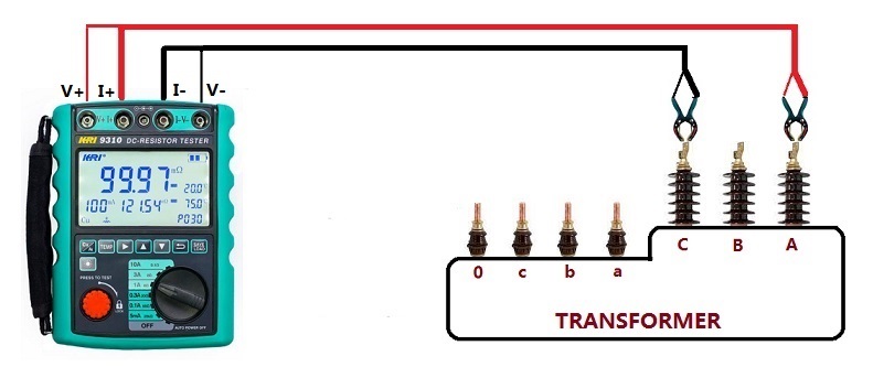
Transformer Winding Resistance Testing Connection:

Use a constant current power supply to apply a current of 1A to a 1mΩ resistor. According to U=IR, it can be calculated that the voltage across the resistor is 1mV.
Obviously, for most measuring instruments, it is more convenient and reasonable to sample and process the voltage signal at the mV level. 1μV is too small, and generally needs to be amplified during measurement, and 1mV is too large, so it needs to be very high. Proportional attenuation is required. Under the condition of constant current, the greater the resistance, the greater the voltage, and the input voltage range of the measuring instrument is limited. Therefore, when measuring large resistances, the test current needs to be reduced to keep the input voltage within a reasonable range. On the contrary, when measuring small resistance, it is necessary to increase the measurement current to match the input voltage, to accurately measure the resistance of small resistance.
At present, the advanced four-wire Kelvin method is generally used to measure DC resistance, which can eliminate the voltage drop caused by wire resistance. The schematic diagram is as follows:
Among them, RL is the resistance to be measured. The V/I constant current power supply FORCE provides the constant current power supply for the test instrument, and the voltage at both ends of RL is measured through the SENSE line. Both FORCE and AGND wires have equivalent resistances. When it is large, a large voltage drop is bound to occur. Since SENSE and DGS are directly connected to both ends of the load, and the input impedance is extremely high, the current flowing through these two wires can be regarded as zero, so that the voltage across load can be accurately read.
A four-wire Kelvin measurement can accurately measure resistance values of less than 0.1 Ω, while subtracting the inherent resistance of the wires connecting the measuring instrument to the component under test. A 24-inch digital multimeter (DMM) test lead typically has a natural resistance of about 0.1Ω. So when two leads are used to connect to the unit under test (UUT), at least 0.2 Ω of additional measurement is produced. In addition, small contamination on the plug leads, whether it is finger grease, dust from the air, or the corroded and oxidized surface of the metal of the object under test, can add additional resistance or cause a change in the measured value when the lead or plug is bent.
What are the advantages and disadvantages of a four-wire Kelvin testing
The main advantage of the four-wire measurement is that it eliminates any effect of the fixture resistance (leads) to obtain the precise resistance value of the UUT. Since four-wire measurements typically use much higher test currents than those required for two-wire tests, a second advantage is high-current stress testing of wiring by driving 1A or more through each wire, and the ability to reduce dwell time Set from 100 milliseconds to minutes – observing slowly increasing resistance during long dwell periods caused by thermal heating may reveal problems not detected by shorter measurement intervals.
The advantages of four-wire measurement come at a price. First, the test system requires twice the number of test points typically required for 2-wire resistance measurements, which greatly increases equipment cost. Second, the test fixture must use two wires for each pin on the mating connector, one for current sourcing and one for voltage sensing. This adds cost and complexity to the test fixture.The application of four-wire Kelvin measurement technology will improve the quality and reliability of your cable and wire harness products. Precision resistance measurements of less than 0.1 Ω will uncover less sensitive or invisible wiring defects, including bad solder joints, incorrect crimps, dented leads, contaminated lead contacts, and incorrectly stressed pinched wires. Resistive losses from these defects can cause overheating or wiring fires in applications carrying more than 1 A of current, or in the case of measurement circuits that take input from precision sensors, false reporting or circuit misoperation. The 4-wire Kelvin resistance method not only yields milliohm or microohm sensitive measurements, but eliminates the effects of any incidental resistance introduced by test leads or test fixtures. To obtain these benefits, however, requires test equipment with twice the number of test points than it would otherwise require, and a test fixture with two wires from the tester to each pin on the mating connector.
Other Related Articles:
The Most Complete Transformer Vector Group Collection with Winding Connection Diagrams
How Important is Transformer DC Winding Resistance?
Top 6 transformer winding resistance testers Worldwide (Including Prices)
How should Winding Resistance be Tested Differently on CT and PT?
What is the Difference between DC Resistance and Insulation Resistance and How to Test Them?
8 Tips to Improve the Accuracy of DC Resistance Measurement
Why is the Tested Winding Resistance Always Inaccurate? You May Have Overlooked These 6 Key Points
Kingrun Transformer Instrument Co.,Ltd.


More Transformer Testers from Kingrun
