Contact resistance refers to the resistance to current flow due to surface conditions and other reasons when the contact surfaces are in contact with each other (in the closed state of the device). This can happen between parts such as disconnector, circuit breakers, relays and switches. The contact resistance test can understand the connection quality of the line and its conductive characteristics, and avoid dangerous overheating of the contacts.

In fact, there is no really clean metal surface in the atmosphere. Even if a very clean metal surface is exposed to the atmosphere, an initial oxide film of several microns will soon be formed. For example, it only takes 2-3 minutes for copper, 30 minutes for nickel, and 2-3 seconds for aluminum to form an oxide film with a thickness of about 2 microns on the surface. Even the particularly stable precious metal gold will form an organic gas adsorption film on its surface due to its high surface energy. In addition, dust and the like in the atmosphere also form a deposited film on the surface of the contact. Therefore, any contact surface is a contaminated surface from a microscopic analysis.
Contact resistance test content
Two common inspections performed on circuit breaker contacts are visual inspection and contact resistance inspection.
1. Visual inspection includes checking the circuit breaker contacts for dents due to arcing and contact wear or deformation.
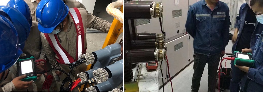
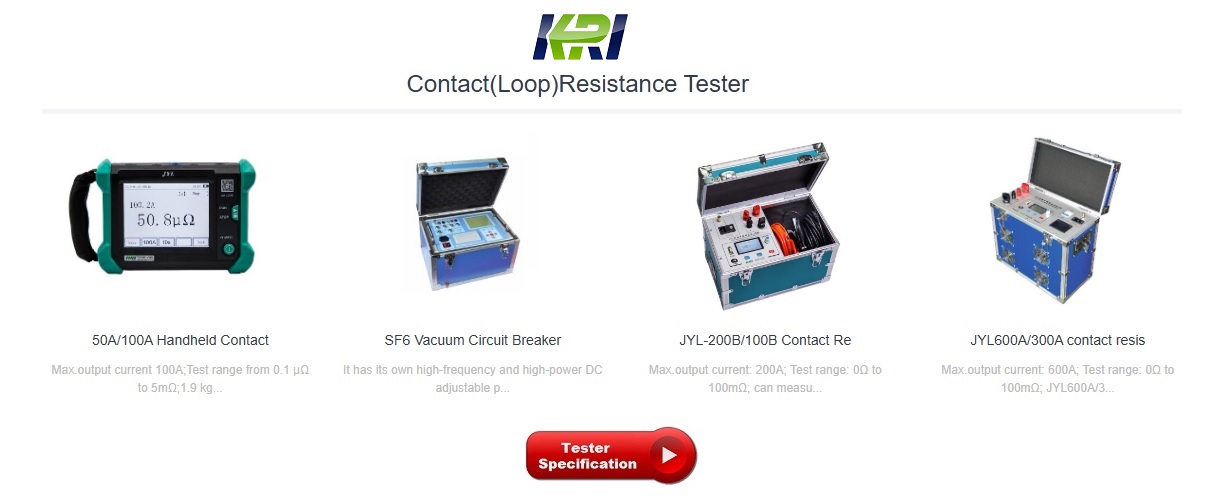
2. The second check is the contact resistance measurement. This involves injecting a fixed current, usually around 100A, 200A and 300A, through the contacts and measuring the voltage drop across it. This test is done using a special contact resistance measuring instrument. Then, use Ohm's law to calculate the resistance value. The resistance value needs to be compared with the value given by the manufacturer. This value should also be compared with previous records.
These two tests need to be done together. Since there are cases where the contactor has good contact resistance but is still in a damaged state. Therefore, for a contactor to prove healthy, it needs to have good contact resistance and should clear the visual inspection test.
The contacts in the circuit breaker need to be checked regularly to ensure that the circuit breaker is healthy and functioning properly. Poor or poor contact can lead to arcing, loss of phase, and even fire. This test is especially important for contacts that carry large amounts of current, such as switchgear busbars, where higher contact resistance results in lower ampacities and higher losses. Contact resistance tests are usually performed using a micro/milliohm meter or a low ohmmeter. The measurement of contact resistance helps to identify fretting corrosion of contacts and can diagnose and prevent contact corrosion. An increase in contact resistance can cause a high voltage drop in the system and needs to be controlled.
Other Related Articles:
Loop Resistance VS Contact Resistance
Hazards and Treatment of Excessive Contact Resistance of Circuit Breakers or HV Switches
How to measure the contact resistance without changing the circuit?
How to Correctly Test the Contact Resistance of HV Switchgear or Circuit Breaker?
Why Does Excessive Contact Resistance Occur In Electrical Secondary Circuits?
What is the Testing Checklist for 110kV/220kV Substation Acceptance and Maintenance Testing?


Kingrun Transformer Instrument Co.,Ltd.


More Transformer Testers from Kingrun