How to Correctly Test the Contact Resistance of HV Switchgear or Circuit Breaker?
The principle of measuring the contact resistance of switches
Contact resistance is defined as the ratio of the voltage across the contacts to the current flowing through a pair of closed contacts. It obeys Ohm's law. There is an interface between Metal 1 and Metal 2. The current I from the current source flows through this interface and can be read from an ammeter. The voltage drop across the interface can then be read as U from a voltmeter, the contact resistance value Rx can then be calculated.
Rx=U/I
Since the contact resistance varies with the environment and the passage of current, the measurement conditions should be close to the usage conditions, accurate measurement must use four-terminal measurement technology and thermal EMF elimination technology. This indirect measurement method can be used to measure contact resistance or loop resistance. It requires three test points, three steps, and three formulas. This method has been proven correct and can also be used to calibrate loop resistance standards.
Typical Methods of Contact Resistance Testing
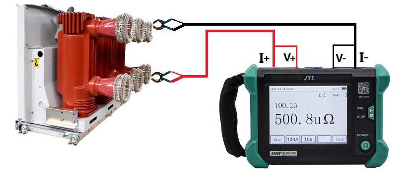
Four-wire (Kelvin) DC voltage drop is a typical method for contact resistance testing with microohm meters, which ensures a more accurate measurement by eliminating both its own contact resistance and the resistance of the test leads.
Contact resistance testing uses two current connections for injection and two potential leads for voltage drop measurement; the voltage cable must be as close as possible to the connection to be tested and always within the circuit formed by the connected current leads.
Based on the measurement of the voltage drop, a microprocessor-controlled micro-ohmmeter calculates the contact resistance while eliminating errors that can arise from the effect of thermal EMF in the connection (a thermal EMF is a small thermocouple voltage created when two dissimilar metals are connected together) they will be added to the measured total voltage drop, and if they are not subtracted from the measurement by different methods (polarity inversion and averaging, direct measurement of thermal EMF amplitude, etc.), errors will be introduced into the contact resistance test.
If a low resistance reading is obtained when testing the circuit breaker contact resistance with a low current, it is recommended to retest the contacts at a higher current. Why would we benefit from using higher current? A higher current will be able to overcome connection problems and oxidation on the terminals, under these conditions a lower current may produce erroneous (higher) readings.
It is important to maintain consistent measurement conditions in contact resistance testing to be able to compare with previous and future results for trend analysis, therefore, when taking periodic measurements, the contact resistance test must be performed in the same location, with the same test leads (always use the manufacturer's calibration cable) and under the same conditions to be able to know when to connect, connect, solder or The device will become insecure.
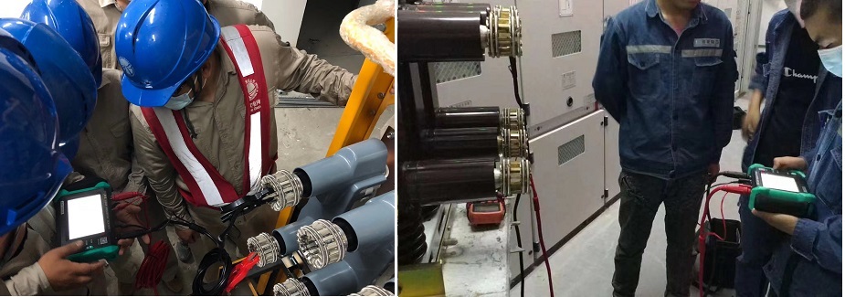
Handheld Contact Resistance Tester--JYL (Kingrun)

Other Related Articles:
Why Does the Contact Resistance Testing Need 100A or Higher?
Hazards and Treatment of Excessive Contact Resistance of Circuit Breakers or HV Switches
How to measure the contact resistance without changing the circuit?
How to Correctly Test the Contact Resistance of HV Switchgear or Circuit Breaker?
Why Does Excessive Contact Resistance Occur In Electrical Secondary Circuits?
What is the Testing Checklist for 110kV/220kV Substation Acceptance and Maintenance Testing?
Kingrun Transformer Instrument Co.,Ltd.


More Transformer Testers from Kingrun


