
Transformer no-load test purpose
Transformer no-load test is a test requirement for 10kv and above transformers.It is by measuring no-load current and no-load loss to analyze the local and overall defects of the transformer magnetic circuit, but also to find the defects of the windings.
In actual measurement, the increase in variable voltage no-load loss is generally caused by short circuit between winding turns, short circuit between winding layers, short circuit of winding parallel branch and the number of turns of each parallel branch, resulting in magnetic potential imbalance and causing no-load current to increase.
Test methods
Transformer no-load test recommended use KRI-JYW6100 Transformer no-load and on-load tester power factor tester.It can measure the transformer no-load and load (short circuit) loss, record zero-sequence impedance, zero-sequence reactance, zero-sequence inductance, impedance angle, zero-sequence resistance.Before testing, from a certain winding of the transformer (generally from the secondary low voltage side) to apply the rated voltage of the sine wave rated frequency, the rest of the windings open circuit.If the test conditions are limited, the power supply voltage can not reach the rated voltage, it can be tested under non-rated voltage conditions, this test method error is large, generally only used to check whether the transformer has a fault, Only if the test voltage reaches more than 80% of the rated voltage can test no-load loss.
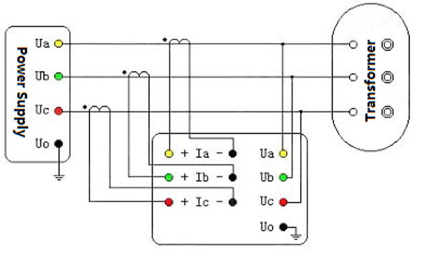
Using a three-phase voltage regulator as the test power supply, the output end of the voltage regulator is connected to the positive end of the current terminal of the tester.The thick line of the three test pliers is connected to the negative end of the current terminal of the tester according to the color.The thin lines of the three test pliers are connected to the voltage terminal of the tester according to the color, and then the three test pliers are clamped to the low-voltage side terminal of the transformer under test, and the yellow pliers are connected to the A phase, the green pliers are connected to the B phase, and the red pliers are connected to the C phase. Open circuit on the HV side.
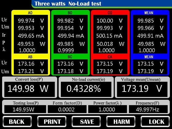
After the wiring is completed, the output voltage of the voltage regulation is slowly adjusted, and the current no-load current and no-load loss can be directly read on the display panel of the JYW6100 Transformer no-load and on-load tester power factor tester.
Precautions
After the withstand voltage test on transformers, it is necessary to retest the no-load loss.After the withstand voltage test,it is also the most possible to find the insulation between the winding turns.Other equipment can also be used to measure the quality of the winding.JYW6100 Transformer no-load and on-load tester power factor tester is not the only option.
Kingrun Transformer Instrument Co.,Ltd.


More Transformer Testers from Kingrun


