Why can't a multimeter test the DC resistance of a transformer?
Because the DC resistance of the primary and secondary windings of the power transformer is very small, the measurement accuracy of the pointer type and digital multimeter is not enough, and the resistance gear cannot accurately measure the low resistance value of the transformer coil resistance. Because the resistance range of the pointer multimeter is limited, it is generally between 0.1-10 times the central resistance of the meter. The internal resistance of the transformer may be very small. For example, the resistance of the secondary coil of a small step-down transformer is less than 1 ohm. At this time, use the pointer multimeter to measure the Rx1 gear, and set the central resistance to 15, which is effective. The minimum measurement resistance is 1.5Ω. For coil resistances less than 1Ω, the data cannot be accurately read, and it can only be judged that it is "on"
DC resistance measuring range of multimeter
1. Measure that the output power of the power transformer is below 5 W, select the Rxk switch, and generally the DC resistance is between 1 and 2kΩ.
2. The output power of the power transformer is 10 W to 100 W, and the DC resistance is several hundred ohms. Select Rx100 when measuring.
3. The output power is more than 100 W, and the DC resistance is between tens to hundreds of ohms, which can be measured with Rx10 switch.
4. In short, the DC resistance of the power transformer is inversely proportional to the output power, that is, the smaller the output power, the greater the DC resistance value, and vice versa.
Measuring range of DC resistance tester
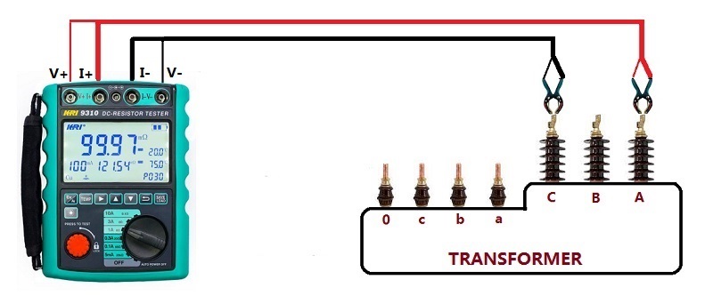
It is a very common test to perform DC resistance of power transformer windings with a DC resistance tester. According to the difference of the current size, when the DC resistance tester determines the specification and model, it is very intuitive to write the current size into the product name, such as: 1A, 3A, 10A DC resistance tester.
When measuring the DC resistance of a transformer, the current of the DC resistance meter should be neither too large nor too small. The principle of selection is to make the iron core saturated as much as possible, and not to change the resistance generator due to the heating of the winding caused by the passing current.

Since the quality of electrical steel sheets used in modern transformers is much higher than in the past, the no-load current of the transformer decreases rapidly. Usually, 2%~10% of the rated current of the transformer is used to measure the DC resistance of the transformer, which can saturate the iron core, and the smaller percentage For large capacity transformers, a larger percentage is used for small capacity transformers.
When the AC no-load current at the rated voltage passes through the transformer winding, there will be a rated magnetic flux density Bn in the iron core, and the magnetic permeability μ of the iron core will be relatively low at this time. When measuring DC resistance, it is necessary to make the magnetic density in the iron core larger than Bn, so that the core conductivity μ becomes lower, in order to reduce the time constant and back electromotive force dLi/dt of the circuit, and shorten the stabilization time.
Therefore, the DC current when measuring DC resistance should be at least
I=k√2i0In÷100
where k——constant>1
i0——AC rated frequency, no-load current percentage value under rated voltage (%)
In——The rated current of the winding under test (A)
In the formula, the constant √2 is the magnitude of the DC current equivalent to the AC current. When the factor k is larger than 1, the magnetic density in the iron core is greater than Bn, which reduces the magnetic permeability μ of the iron core when measuring the DC resistance.
When the transformer windings are star (Y) connected, the line current is equal to the phase current. From the above formula, it can be concluded that the current that should be applied when measuring the DC resistance is
IY=1.41 ki0In÷100
When the transformer windings are connected in a delta (D), the variable no-load current line current is √3 times the phase current, and the DC current when measuring the DC resistance is based on the ratio of 1/3 and 2/3 of the total current distributed. Therefore, the current should be applied to measure the DC resistance is
ID=1.41×3/2÷1/√3 ki0In×100=1.22 ki0In÷100
When k is 3~10, that is, the excitation ampere-turn when measuring the DC resistance is 3~10 times that of the no-load current ampere-turn, the magnetic density in the iron core can be made larger than Bn and close to saturation, that is, the DC resistance when measuring the DC resistance is taken. The current is equal to 2% - 10% of the rated current. If the DC current during measurement is too large and the measurement time is too long, the resistance will change due to the increase in the heating temperature of the winding, which will increase the measurement error.
The above formulas can accurately select the appropriate current value. Of course, now the general manufacturers will also specify the detailed test plan for the customer according to the parameters of the tested product, and do not need to calculate very hard. However, it is also a good thing to live to old age, learn old age, and master a skill by oneself.

Kingrun Transformer Instrument Co.,Ltd.


More Transformer Testers from Kingrun


