What is the DC Winding Resistance of Transformer&Motor and How is it Tested?
DC resistance is an important parameter of motor windings. It is related to many factors such as the design of the motor winding, the material of the magnet wire used, and the ambient temperature. In the process of motor inspection test and type test, DC resistance detection is a must-tested item; for motor companies that standardize production, DC resistance detection will be carried out before the motor winding iron core is dipped in paint, so as to avoid unsatisfactory requirements. The product enters the subsequent production link.
Determination of DC resistance is also an important part of the motor test. Through the analysis of the measured resistance value, it can be preliminarily determined whether the number of turns, wire diameter, number of parallel windings, wiring method and wiring quality of the tested motor windings meet the requirements, and whether there is a serious short-circuit fault between the winding turns. The DC resistance of the winding is involved in the calculation of motor loss and temperature rise, which directly affects the effect of motor performance evaluation. Therefore, the measurement test of the DC resistance of the winding should choose a test instrument with a higher precision, and strive to have a higher accuracy of the detection data.
When measuring the DC resistance of the winding in the motor test, the DC resistance measuring instrument (such as resistance tester, DC bridge, etc.) is generally used for direct measurement, and sometimes the voltage and current methods are used (generally not used).
Measurement of DC Resistance of Three-Phase Windings
The stator of the three-phase AC asynchronous motor and the synchronous machine, and the rotor of the three-phase wound motor have three-phase symmetrical windings. In the national motor standard, the DC resistance measurement method for these windings is specified. During the measurement, the temperature of the winding to be measured should be measured. If the motor is in an actual cold state, the ambient temperature can be used to correct the temperature. When conducting type tests or other tests that require accurate results, measure each phase resistance or each line resistance 3 times, and then take the average value of the 3 times as the measurement result.
● Direct measurement of phase resistance
When the three-phase windings of the stator or rotor of the motor are all drawn from the head and tail of each phase, or the three-phase windings have been connected to a star (Y-shaped) in the motor, but the neutral wire ( When the star point) is also drawn out, the DC resistance of each phase can be measured separately.
● Measuring line resistance
When the three-phase windings of the stator and rotor of the motor have been connected to a star (Y) or a triangle (△) inside the motor, only the resistance (ie, line resistance) of each two outer wire ends can be measured, and then the corresponding phase resistance can be converted by the formula.
Conversion of line resistance to phase resistance
If the phase resistance of the winding is R phase and the line resistance is R line, the calculation of the line resistance can be calculated according to the series-parallel principle of resistance.
●Convert line resistance from phase resistance
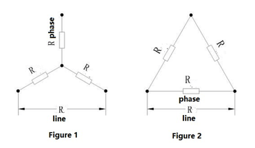
When the motor winding is star-connected, the schematic diagram is shown in Figure 1, R line = 2R phase.
 When the motor winding is angularly connected, the schematic diagram is shown in Figure 2, R line=2R phase/3.
●Convert phase resistance from line resistance
The formula for calculating line resistance from phase resistance under different connection methods can be mathematically converted.
When the motor winding is star-connected, the schematic diagram is shown in Figure 1, R phase = 0.5R line
When the motor winding is angular connection, the schematic diagram is shown in Figure 2, R phase = 1.5R line.
●Conversion of resistance value at different temperatures
Generally, the DC resistance of a metal conductor has a fixed relationship with its temperature. This relationship is expressed as:
R1=R2×(K+t1)/(K+t2)…………(1)
In the formula: R1——the DC resistance (Ω) when the temperature is t1℃;
R2——DC resistance (Ω) when the temperature is t2℃;
K——Constant (at 0℃, the reciprocal of the temperature coefficient of conductor resistance), for copper windings, K=235, for aluminum windings, K=225.
●Resistance standard under different test conditions
In the type test report, the specific resistance value will be given according to the different insulation grades of the motor. For example, the resistance of the B-class insulation motor is at 75°C, while the F-class insulation motor is the resistance at 95°C, and the H-class insulation motor is Resistance at 105°C. In the inspection test evaluation standard, it is customary to give the resistance at 20°C. When the temperature deviates, it can be converted according to formula (1).
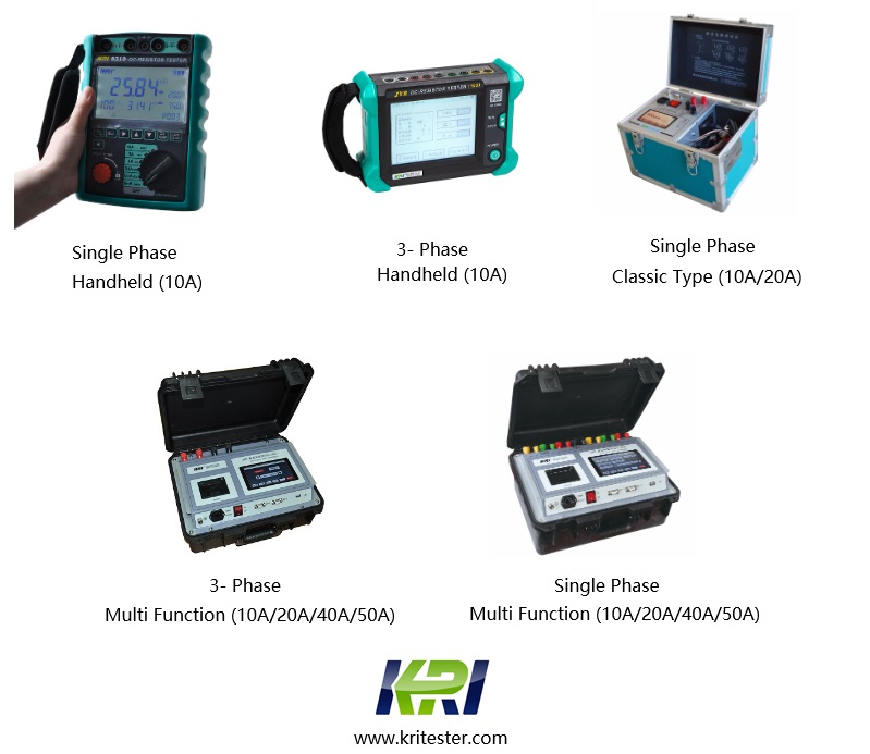
KRI 9310 transformer winding resistance tester is suitable for small distribution transformer (below 80KVA) it is provided with the temperature conversion function. By selecting test sample material(copper/aluminum) and temperature from tester, the instrument can be able to automatically convert them to the resistance values under the standard temperature (20℃,75℃,120℃). KRI 9310 is also provided with the data storage function, 500 groups of experimental data can be stored within the instrument. also KRI 9310 has USB interface, the data can be down load to flash disc.
Related Articles:
The Most Complete Transformer Vector Group Collection with Winding Connection Diagrams
How Important is Transformer DC Winding Resistance?
Top 6 transformer winding resistance testers Worldwide (Including Prices)
How should Winding Resistance be Tested Differently on CT and PT?
What is the Difference between DC Resistance and Insulation Resistance and How to Test Them?
8 Tips to Improve the Accuracy of DC Resistance Measurement
Why is the Tested Winding Resistance Always Inaccurate? You May Have Overlooked These 6 Key Points
Kingrun Series DC Winding Resistance Testers


Kingrun Transformer Instrument Co.,Ltd.


More Transformer Testers from Kingrun


