Causes and Solutions of Partial Discharge in Transformers
Partial discharge is mainly the discharge that occurs in the internal insulation of transformers, transformers and other high-voltage electrical equipment under the action of high voltage. This kind of discharge only exists in the local position of the insulation, and will not immediately form the entire insulation penetration breakdown or flashover, so it is called partial discharge. The amount of partial discharge is very weak and cannot be detected by people's intuition, such as hearing with eyes and ears, and only a highly sensitive partial discharge measuring instrument can detect it.
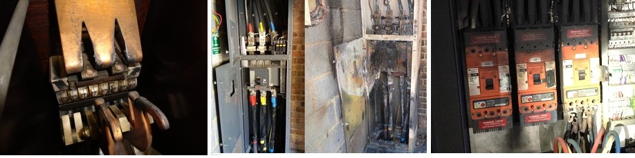
The internal insulation of the transformer is under the action of the working voltage for a long time during operation, especially with the increase of the voltage level, the electric field strength value of the insulation is very high, and it is easy to generate partial discharge in the weak insulation. The reason for the partial discharge is: the electric field Too concentrated on a certain point, or the electric field strength at a certain point is too large, such as solid medium with bubbles, impurities are not removed; oil contains water, gas, and suspended particles; in different medium combinations, there is serious electric field distortion at the interface . Partial discharge traces often leave only a small spot on solid insulation, or a dendritic burn. In the oil, some small bubbles of decomposition appear.
Although the partial discharge time is short and the energy is small, it is very harmful. Its long-term existence will cause great damage to the insulating material. First, the insulating material adjacent to the partial discharge will be directly bombarded by the discharge particles. The second is the chemical action of active gases such as heat, ozone, and nitrogen oxide generated by the discharge, which causes the local insulation to be corroded and aged, and the conductance increases, which eventually leads to thermal breakdown. In the transformer in operation, the aging and damage of the internal insulation mostly starts from partial discharge.
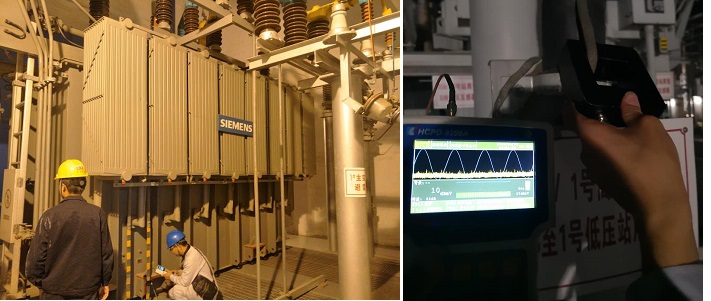
Transformer partial discharge detection methods generally include:
1. Electrical measurement method. Use an oscilloscope or radio interference meter to find the characteristic waveform of the discharge or the level of radio interference.
2. Ultrasonic Testing. The sound waves appearing in the discharge are detected, and the sound waves are converted into electrical signals, recorded on a tape for analysis, and the distance from the detection point to the discharge point can be obtained by using the difference in transmission time between the electrical signal and the sound signal( tester type: GTPD-3 ultrasound partial discharge detector).
3. Chemical test. Detect the content of various dissolved gases in the oil and the law of increase and decrease. This test finds changes in the composition, proportions, and quantities in the oil to determine the presence or absence of partial discharge (or localized overheating).
Measures to reduce partial discharge of transformers
1. Dust control
Among the factors that generate partial discharge, foreign matter and dust are very important inducements. The test results show that metal particles with a diameter of ф1.5μm may generate discharges far greater than 500pC under the action of an electric field. Whether metal or non-metal dust exists, a concentrated electric field will be generated, which will reduce the initial discharge voltage of the insulation and reduce the breakdown voltage. Therefore, in the transformer manufacturing process, it is very important to maintain a clean environment and body, and dust control must be strictly implemented. Strictly control the degree to which products may be affected by dust during the manufacturing process, and establish a sealed and dust-proof workshop. For example, foreign matter residues and dust are not allowed to enter during wire leveling, wire wrapping, winding winding, winding set, core stacking, insulation manufacturing, body assembly and body finishing. Strictly control the degree to which products may be affected by dust during the manufacturing process, and establish a sealed and dust-proof workshop. For example, foreign matter residues and dust are not allowed to enter during wire leveling, wire wrapping, winding winding, winding set, core stacking, insulation manufacturing, body assembly and body finishing.
2. Centralized processing of insulating parts
It is very taboo for insulating parts to contain metal dust, because once the insulating parts are attached to metal dust, it is very difficult to completely remove it. Therefore, it is necessary to centralize processing in the insulation workshop, and set up a machining area, which should be isolated from other areas that produce dust.
3. Strictly control the processing burrs of silicon steel sheets
Transformer core pieces are formed by longitudinal shearing and transverse shearing. These shearing cuts have different degrees of burrs. The burr can not only cause short circuit between chips, form internal circulation, increase no-load loss, but also increase the thickness of the iron core, which actually reduces the number of laminated chips. More importantly: when the iron core is inserted into the yoke or subjected to vibration during operation, the burr may fall on the body and discharge may occur. Even if the burr falls on the bottom of the box, it may be arranged in an orderly manner under the action of the electric field, causing the ground potential discharge. Therefore, the core burr should be as small as possible. The burr of the core piece of 110KV product should not be larger than 0.03mm, and the burr of the core piece of 220KV product should not be larger than 0.02mm.
4. The lead adopts cold-pressed terminal
The use of lead cold-pressed terminals is an effective measure to reduce the amount of partial discharge. Because a lot of spatter welding slag is generated when using phosphor copper welding, it is easy to be scattered in the body and insulating parts. In addition, the welding boundary area needs to be separated by water soaked asbestos rope, so that water can enter the insulation. If the moisture is not completely removed after the insulation wrapping, it will increase the partial discharge of the transformer.
5. Rounding of component edges
The purpose of rounding the edge of the parts is: 1) To improve the distribution of the field strength and increase the initial voltage of the discharge. Therefore, the metal structural parts in the iron core, such as clips, pull plates, pads and bracket edges, pressure plates and wire outlet edges, the wall of the casing riser, and the magnetic shielding shield on the inner side of the box wall, should be rounded. 2), to prevent friction from producing iron filings. For example, the contact part between the lifting hole of the clip and the lanyard or hook should be rounded.
6. Product environment and body finishing during final assembly
After the body is vacuum-dried, the body should be sorted out before packing. The larger the product and the more complex the structure, the longer the finishing time will be. Since the body is compressed and the fasteners are tightened, the body is exposed to the air, and moisture absorption and dust scattering will occur during the period. Therefore, the body should be cleaned in a dust-proof area, such as finishing time (or exposure to the air). time) more than 8 hours, it needs to be dried again. After the finishing of the body is completed, the stage of vacuuming and filling the fuel tank is carried out. Because the insulation of the body will absorb moisture during the body finishing stage, it is necessary to dehumidify the body. This is an important measure to ensure the insulation strength of high-voltage products. The method adopted is to vacuum the product. Determine the vacuum degree of vacuuming according to the body, ambient humidity and water content standards, and determine the vacuuming time according to the release time, ambient temperature and humidity.
7. Vacuum oiling
The purpose of vacuum oil injection is to remove the dead angle in the insulation structure of the product by evacuating the transformer, exhaust the air completely, and then inject the transformer oil in a vacuum state to completely soak the body of the transformer. The transformer after oil injection can be tested after standing for at least 72 hours, because the degree of penetration of the insulating material is related to the thickness of the insulating material, the temperature of the insulating oil, and the time of immersion in the oil. The better the degree of penetration, the less possibility of discharge, so be sure to allow enough rest time.
8. Sealing of fuel tank and parts
The quality of the sealing structure is directly related to the leakage of the transformer. If there is a leakage point, moisture will inevitably enter the inside of the transformer, resulting in moisture absorption of the transformer oil and other insulating parts, which is one of the factors of partial discharge. Therefore, it is necessary to ensure the reasonable sealing performance.
Kingrun Transformer Instrument Co.,Ltd.


More Transformer Testers from Kingrun


