
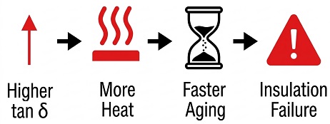
Tan Delta testing is a crucial method for assessing the condition of a transformer's insulation system. Tan Delta, also known as the loss angle tangent, is the ratio of the active current component to the reactive current component in insulating materials, reflecting the dielectric loss of the insulation. Fundamentally, healthy insulation stores energy, while bad insulation wastes it as heat. Simply put, the smaller the tan δ value, the lower the dielectric loss of the insulating material, and the better its insulation performance. By measuring the tan δ value, the aging degree and moisture condition of the transformer's insulation materials can be evaluated, allowing for the early detection of potential insulation failures.
Dielectric loss: Under the action of an electric field, the energy loss inside the insulating material due to the hysteresis effect of dielectric conductance and dielectric polarization. Also called dielectric loss, referred to as dielectric loss. Under the action of the alternating electric field, the complementary angle δ of the included angle (power factor angle Φ) between the current phaser and the voltage phaser flowing in the dielectric is called the dielectric loss angle.Under the action of the alternating electric field, the charge accumulated in the dielectric has two components:
(1) Active power. One is the power consumed for heating, also known as the in-phase component;(2) Reactive power, also known as out-of-phase component. The ratio of the out-of-phase component to the in-phase component is called the dielectric loss tangent tanδ. tanδ=1/WCR (where W is the angular frequency of the alternating electric field; C is the dielectric capacitance; R is the loss resistance). The dielectric loss tangent is a dimensionless physical quantity.

Hysteresis loss
The hysteresis loss is due to the existence of a "hysteresis loop" in the iron core, so that the phase difference between the induced electromotive force and the magnetizing current is not equal to 90 degrees. We know that if it is 90 degrees, the current is "reactive". Now it is not equal to 90 degrees, which is equivalent to connecting an active current component in parallel.
By Steinmetz formula hysteresis loss,
Kh – hysteresis constant
Wh – Hysteresis loss per unit volume.
Kh – Hysteresis coefficient (depending on the core material)
f – Frequency of the magnetic field.
Bm –Maximum magnetic flux density.
Eddy Current loss,
We= Ke . f2 . Bm 2.t 2 ( W/m3)
Ke – co-efficient of eddy currentWe –Eddy current loss per unit volume.
Ke –Eddy current coefficient (dependent on the material's resistivity)
f –Frequency of the alternating magnetic field.
Bm –Maximum magnetic flux density.
t –Thickness of the steel laminations (sheets).
Eddy current loss can be reduced by using an iron core made of thin laminated sheets and material with high electrical resistivity. It reduces the induced EMF and the amount of current flow.
2. Specific explanation:
When the transformer is working normally, the magnetic field generated by the secondary side current and the main part of the primary current are offset. The magnetic field left after cancellation should be roughly equal to the magnetic field at no load (when the secondary current is zero) (assuming resistance and leakage flux are ignored). Therefore, the "magnetizing current" I mentioned above should be equal to the no-load current of the transformer.When the transformer is no-load, if there is no loss, the input characteristics of the primary side should be equivalent to a pure inductance. With loss, the input current is equivalent to adding a resistor in parallel to the inductor. tanδ should be equal to the ratio of the current on this equivalent resistor to the current on the inductor.

Other transformers loss types:
1. Iron Losses or Core LossBoth the Eddy current loss and hysteresis loss depend upon the magnetic properties of the core material, f-frequency of the AC supply and the Bm– maximum flux density.
Total Copper Loss, Pcu = I12R1 + I22R2;
The values of Resistance R1 of the primary winding and R2 of the secondary winding are constant.
It occurs in the insulating material and oil of the transformer. The transformer oils are subject to change its parameters such as dielectric strength, tan delta, moisture, chemical parameters (dissolved impurities – dissolution of copper), physical parameters, etc…
Additional points
1.Iron loss (Hysteresis loss, eddy current loss) and dielectric loss are no-load losses which are independent of the transformer load.
2.Whereas the copper loss and stray loss varies with the load current.
3.Iron loss is a constant loss and copper loss is a variable loss.
4.Copper loss is determined by the short circuit test and Iron loss is determined by the open circuit test.
Measuring tan Delta is of significant importance for transformers. Firstly, it helps identify the aging and deterioration of the internal insulation. Over time, the insulation materials in a transformer degrade due to electrical stress, thermal stress, and environmental influences, resulting in decreased dielectric performance and increased tan δ values. Regular measurement of the tan δ value allows for maintenance and repair before problems escalate into serious faults, preventing sudden power outages and equipment damage. Secondly, tan Delta measurement can detect moisture conditions in the transformer windings. Moisture in insulation materials significantly increases the tan δ value, potentially leading to insulation breakdowns and short-circuit faults. Through regular measurements, moisture issues can be identified and addressed early, ensuring the safe operation of the transformer. Additionally, tan Delta testing can be used for quality control and acceptance of new equipment, ensuring compliance with technical specifications and performance standards.
In summary, tan Delta measurement is a critical step in transformer maintenance. Regular monitoring of insulation status can effectively extend the transformer's service life, reduce the risk of failures, and enhance the reliability and safety of the power system.
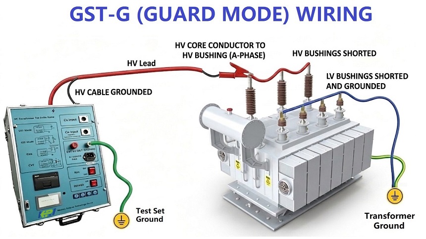
The following diagrams illustrate three typical wiring configurations for Power Factor (Tan Delta) testing of transformers and bushings:
GST-G (Grounded Specimen Test with Guard): This mode is used for testing the overall insulation to ground of a grounded transformer. The high-voltage windings are shorted and energized, while non-test windings are grounded. The tester utilizes a guard circuit to bypass stray ground currents, enabling precise measurement of the main insulation—a core method for transformer body insulation diagnosis.
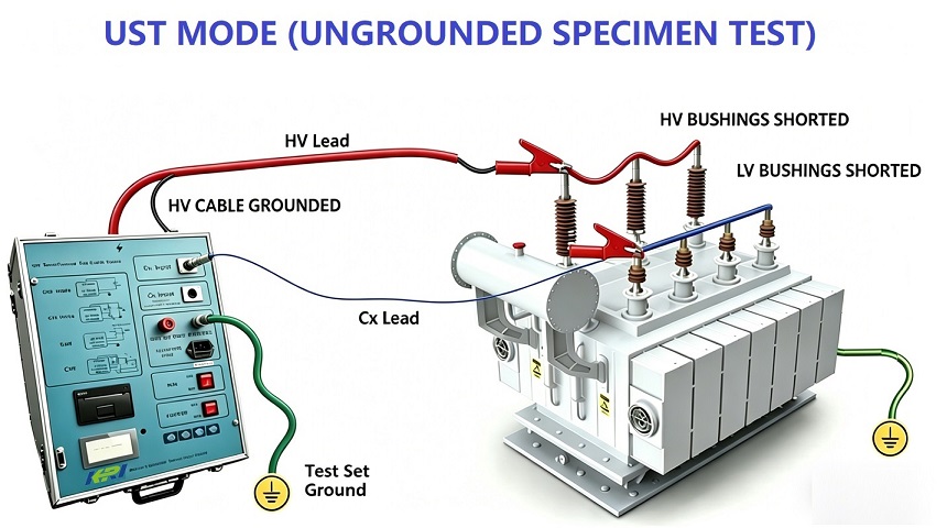
UST (Ungrounded Specimen Test) - Transformer Mode: This configuration is specifically designed to evaluate the insulation between windings. The high-voltage winding is energized, and the low-voltage winding is connected as the signal input. Since the specimen is ungrounded on both sides, this mode directly measures the inter-winding insulation loss, completely eliminating the influence of leakage currents to ground for high-precision results.
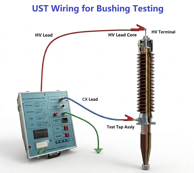
UST - Bushing Test Mode: This mode is dedicated to testing the main insulation (C1) of capacitive bushings. The high-voltage lead is connected to the top of the bushing, and the test tap is used as the signal output to the instrument. This wiring directly assesses the level of insulation degradation within the bushing, providing critical data for determining whether high-voltage bushing replacement is necessary.
Together, these three modes complement each other, providing comprehensive insulation performance testing covering both the transformer body and its key components.
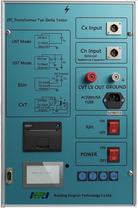
Transformer Tan Delta Tester (JYC)

To ensure data validity and personnel safety, the following conditions must be met before entering the test site:
Isolation and Discharge: All high-voltage and low-voltage connections must be disconnected. The transformer must be completely de-energized and all windings must be reliably grounded to discharge residual charges.
Environmental Recording: Record ambient temperature and humidity. Since Tan Delta values are highly temperature-sensitive, values must typically be corrected to a 20°C standard reference.
Surface Cleaning: Clean the bushing porcelain/sheds and terminals to remove dust, oil, or moisture. This prevents surface leakage currents from distorting the measurement accuracy.
Equipment Self-Check: Verify the tester’s grounding, ensure shielded cables are intact, and perform an open-circuit/short-circuit self-test.
Select the appropriate wiring configuration based on the test object. Below are the three core operational modes:
Application: Measuring the insulation of a grounded transformer component (e.g., HV windings to ground).
Operational Logic:
High-Voltage Output (HV): Connect to the terminal of the winding under test.
Test Input (Cx): Not connected (measurement is performed internally via the ground return).
Guard: Connect non-test windings (e.g., LV windings) to the Guard terminal.
Objective: The Guard circuit bypasses stray currents from non-test components, ensuring only the target main insulation is measured.
Application: Measuring inter-winding insulation (e.g., HV winding to LV winding).
Operational Logic:
High-Voltage Output (HV): Connected to the HV winding.
Test Input (Cx): Connected to the LV winding.
Logic: Both sides of the specimen are "floating" (isolated from ground). The current flows through the dielectric material directly into the measurement circuit.
Advantage: This eliminates the influence of stray ground capacitance, providing the highest precision for analyzing complex internal insulation.
Application: Specialized insulation layer detection for capacitive bushings.
HV Lead: Clipped to the bushing top (HV Terminal).
Cx Lead: Clipped to the bushing Test Tap (End Shield).
Critical Step: Ensure the test tap grounding screw is removed and the tap is floating. This is the most direct method for assessing internal bushing degradation.
C2 Insulation Test (Optional):
To measure the insulation between the test tap and the ground flange, the tap is used as the HV input while the flange remains grounded.
Voltage Ramping: Gradually increase the test voltage. Observe data stability; sudden jumps in Tan Delta during ramping often indicate internal partial discharge or insulation defects.
Temperature Correction: Tan Delta increases exponentially with temperature. After testing, use standard correction factors to convert the measured value to 20°C for meaningful comparison with factory data.
Comprehensive Evaluation:
Trend Analysis: Compare against historical records (longitudinal).
Benchmark: Compare against similar units (lateral) and manufacturer nameplate standards.
Anomalies: High values may indicate moisture ingress, oil aging, carbon tracking, or water leakage in the bushing.
Safety Discharge: After testing, the test equipment and the specimen must be fully discharged before removing any leads.
Interference Suppression: In high-interference environments (e.g., energized substations), ensure the use of frequency-shifting (Variable Frequency) technology to filter out EMI.
Documentation: Every test report must include: Testing mode, ambient parameters, frequency, voltage level, Tan Delta value, and Capacitance (pF).
 JYC automatic frequency conversion anti-interference dielectric loss tester is used for field anti-interference dielectric loss measurement or laboratory precision dielectric loss measurement,the instrument is an integrated structure, built-in dielectric loss bridge, variable frequency power supply, test transformer and standard capacitor, etc., adopts frequency conversion anti-interference and "Fourier" transform digital filtering technology, fully automatic intelligent measurement, the measurement data is very stable under strong interference, and the measurement results are from large to large, LCD screen display, built-in printer can print out.
Kingrun Transformer Instrument Co.,Ltd.


More Transformer Testers from Kingrun


