The initial transformer turns ratio (TTR) testing was conducted using a simple bridge method, such as the Maxwell or Heaviside bridges, these early devices required a series of complex, separate components—standard resistors, inductors, and galvanometers—making the testing process time-consuming, labor-intensive, and prone to calculation errors (left side of the bottom picture).

The development of transformer turns ratio (TTR) testers dates back to the early 20th century, with the hand-cranked transformer ratio testers developed by James G. Biddle,operators needed to generate excitation voltage by turning a hand-cranked generator on the side while adjusting a knob until the galvanometer pointer zeroed out (zero-balance method), and then reading the turns ratio from the scale on the knob (right side of the top picture).
By the late 20th century, the advent of microprocessors led to the creation of digital TTR testers, these devices automated the excitation and balance processes, displaying readings on an LCD screen instantly and eliminating human errors. Modern devices are now fully automated, capable of testing all three phases simultaneously, measuring phase shift and excitation current, and offering wireless data logging capabilities, from the bulky, hand-cranked wooden testers to the handheld high-precision computers, TTR testers have continuously evolved to meet the demands of the increasingly complex global power grid.
The JYT-A TTR utilizes a high-precision multi-core ARM CPU (Advanced RISC Machines, USA), delivering exceptional measurement accuracy and resolution. This fully automatic three-phase testing instrument is specifically designed for determining the turns ratio of power transformers, distribution transformers, and instrument transformers. By applying voltage to the high-voltage winding, it precisely measures the no-load voltage on the transformer windings and calculates the turns ratio by displaying the ratio of these voltages.
Based on state-of-the-art technology, the JYT-A is suitable for testing single-phase and three-phase transformers, as well as CTs, PTs, CVTs, Z-type windings, and transformers with or without neutral points and taps. It fully complies with the requirements of IEC 60076-1.
The JYT-A TTR supports testing of various transformer configurations—including single-phase, delta-star, star-delta, delta-delta, star-star, and delta-zigzag—without the need to change connection cables during measurement. Tests can be performed directly, saving time and reducing the risk of connection errors. The instrument can automatically compare test results against the nameplate voltage values entered by the user, calculate the turns ratio deviation, and print the percentage error for each measurement. Even if no reference data is provided, it can still measure the transformation ratio with high precision.
The JYT-A also features multiple protection mechanisms, including high- and low-voltage reverse connection protection, transformer short-circuit protection, and inter-turns short-circuit protection. Its excellent capability to suppress electrostatic and electromagnetic interference in high-voltage environments ensures accurate and reliable test results.


FUNCTION INTRODUCTION:
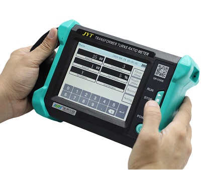
1.The interface adopts intelligent touch mode, which is simple and convenient to operate.The interface adopts an intelligent touch mode, which is simple and convenient to operate.
2.High-stability sine wave power supply; the test voltage is automatically adjusted according to the load.
3.The test data is accurate when the generator is powered, even if the quality of the power supply in the field is poor.
4.The test speed is fast. The three-phase turns ratio test can be completed in one wiring, taking only 10 seconds.
5.CT, PT, CVT, and Z-connection transformers can be tested.
6.It is suitable for ratio measurement of distribution transformers distribution transformers and power transformers, current transformers (CT), voltage transformers (PT), and Z-type transformers.
7.A variety of short circuit measurement methods are available, making fault judgment more convenient.
8.No real-time clock or date display; stores up to 200 records, and data is retained even after power loss.
9.Large color LCD display, with clear and easy-to-read data. RS485 communication interface and USB storage interface.
10.The instrument has high and low voltage reverse connection protection, as well as transformer short circuit and inter-turns short circuit protection.
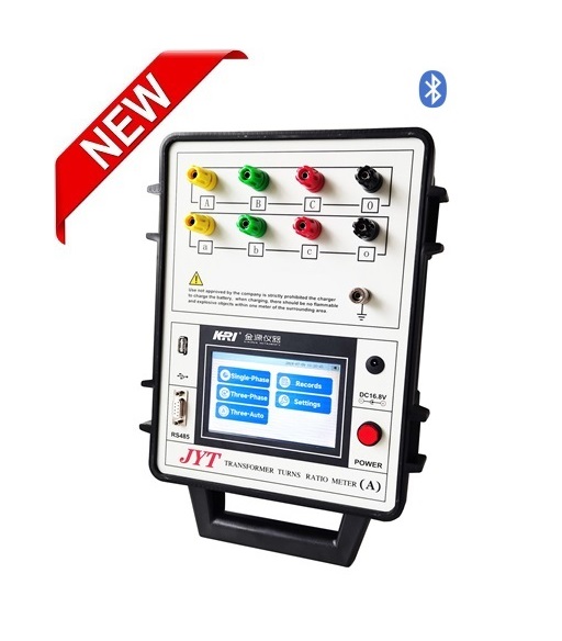
11.Bluetooth communication function (optional).
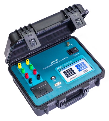
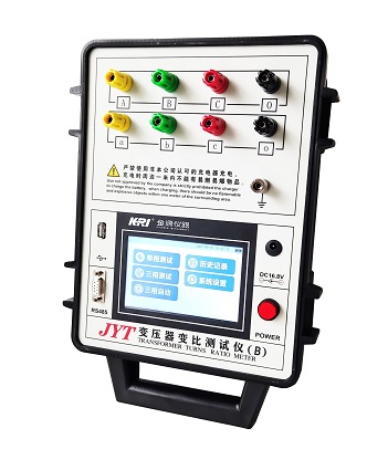
JYT-A Connection with Transformer:


JYT-A TTR function interface and test result interface:

JYT-A TTR Technical Specifications:
|
Output Line Voltage |
≤160V AC(RMS) |
|
|
Ratio Range |
0.9-10000 |
|
|
Accuracy |
Ratio <2000 |
±0.1% |
|
Ratio 2000-10000 |
±0.3% |
|
|
Min. Resolution |
0.0001 |
|
|
Operation Power |
AC100-240V,50/60Hz, or lithium battery (Option) |
|
|
Operating Temperature |
-20℃~40℃ |
|
|
Relative Humidity |
≤80%RH, no condensation |
|
|
Dimensions (L × W × H) |
L285mm x W218mm x H158mm |
|
|
Net Weight |
5 kg |
|
|
Data Storage |
200 sets |
|


FAQ: Transformer Turns Ratio (TTR) Testing:
1. What is the difference between Transformation Ratio and Turns Ratio?
The main difference lies in the relationship between "theoretical values" and "actual measured values," and their applicable scenarios:
1.Turns Ratio: The ratio of the number of turns in the high-voltage winding to the low-voltage winding (N1/N2). This is a theoretical design value determined by the manufacturer and marked on design drawings; it is fixed.
2.Transformation Ratio: The ratio of the voltage of the high-voltage winding to the low-voltage winding (U1/U2). This is the actual value during testing or operation. In an ideal state (ignoring losses and magnetic leakage), the Transformation Ratio ≈Turns Ratio. In practice, factors like losses and load variations cause slight deviations.
3.Purpose: Turns ratio is used for design and production verification; transformation ratio is used for operation, maintenance, and detecting if the windings are functioning correctly.
4. What are Ratio Polarity and Vector Group?
1.Polarity reflects the direction of the "like-ends" (terminals with the same instantaneous polarity).
2.Vector Group (e.g., Dyn11) reflects the phase displacement between the primary and secondary voltages. The tester must automatically identify these to ensure the transformer is correctly integrated into the power system.
There is no single fixed range. The result must comply with the deviation standards relative to the nameplate parameters:
1.Distribution Transformers ( ≤35kV, ≤1000kVA): Allowed deviation ≤ ± 0.5%.
2.Power Transformers (> 35kV, > 1000kVA): Allowed deviation ≤ ± 0.2%..
3.Three-winding Transformers: Each winding must meet the above standards, and there should be no sudden changes (which could indicate a fault).
Yes, they require regular calibration to ensure accuracy and prevent misjudgment of faults.
1.Routine Calibration: Once a year by a qualified metrology institute.
2.Special Circumstances: After repairs, after being idle for over 6 months, or if test data appears consistently abnormal.
3.Industry Requirements: Power grid companies and formal O&M units must ensure instruments are within their valid calibration period per metrological regulations.
Troubleshooting Steps: Re-check wiring ——> Discharge the transformer and re-test ——> Clean terminals and tighten connections ——> If the deviation persists, perform insulation and winding deformation tests to confirm internal damage.
12. How should the test voltage be selected?
The core principle is to match the winding insulation level to prevent damage while ensuring accuracy:Routine Selection: For medium/low voltage transformers (≤ 35kV), use default voltages (e.g., 10V, 20V). For high voltage transformers (> 35kV), use higher voltages (e.g., 50V, 100V) for signal stability.Special Requirements: If insulation is weak, lower the voltage (ensure accuracy is still maintained). Never exceed the instrument’s rated output to avoid damage.
Kingrun Transformer Instrument Co.,Ltd.


More Transformer Testers from Kingrun