In the preventative testing and commissioning of power transformers, the winding Resistance Test is a core indicator for evaluating winding manufacturing quality, tap changer contact performance, and the reliability of lead connections. Due to the significant electromagnetic inertia of transformers, the testing process is essentially a dynamic balancing act within a high-inductance circuit, making it highly susceptible to magnetic saturation, environmental interference, and temperature fluctuations. Minor measurement errors can not only lead to misjudgments of equipment status but may also mask severe structural defects. Therefore, mastering the interference mechanisms and establishing standardized operational procedures is essential for every power professional to ensure the safe operation of equipment.
Errors originating from the wiring stage typically account for more than 50% of anomalous field data.
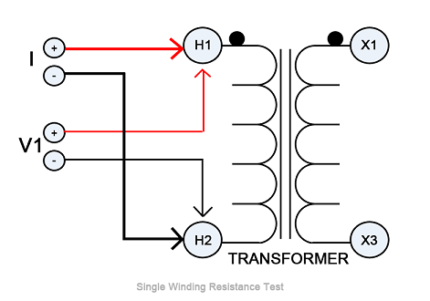
Failure Scenarios of the Kelvin Four-Wire Method:
Mechanism: It is imperative to ensure that the current leads (I+ / I-) are placed on the outside of the sampling points, while the voltage leads (V+ / V-) are on the inside.
Typical Error: A common "single-clamp" approach (where current and voltage contacts are shorted inside the clamp) is often seen in the field. This causes the contact resistance between the clamp and the bushing to be included in the results, with errors reaching up to 0.5Ω. For a low-voltage winding in the 1mΩ range, this creates a 500-fold false deviation.
Terminal Oxidation and Torque Effects:
The contact resistance of an oxide layer is not only high but also non-linear. Terminals must be polished to a metallic luster with fine sandpaper before measurement.
Loose Leads: Micro-ohm level variations caused by loose internal bushing nuts can generate thermal EMF interference under high DC currents.

The electrical time constant t= L / R of the transformer winding is the core factor determining measurement efficiency and accuracy.
Saturation and the Charging Process:
The inductance L of a large transformer can reach hundreds of Henrys. During the initial stage of current buildup, most of the voltage drops across the inductor (uL = L.di/dt).
Stability Criterion: Readings should only be taken when the rate of current change di/dt approaches zero and the resistance reading fluctuates by less than 0.1% within one minute.
Magnetic Assist and Remanence Effects:
Magnetic Assist Method: For large-capacity transformers (such as five-limb cores or LV delta connections), the HV and LV windings can be energized in series. Utilizing the turns-ratio advantage of the HV side accelerates core saturation and significantly reduces test time.
Remanence Trap: If the direction of residual magnetism is opposite to the test current, the current rises extremely slowly. It is recommended to average measurements from both forward and reverse currents to eliminate systematic errors caused by hysteresis loop asymmetry.
Winding resistance tests involve measuring weak DC signals that are easily "drowned out" by environmental interference at high-voltage sites.
Power-Frequency Induced Voltage:
Near 220kV or 500kV operational busbars, the closed loop formed by the test leads couples with power-frequency AC voltage. Since winding resistance testers cannot fully filter out this interference, it results in rhythmic fluctuations in the readings.
Countermeasure: Use shielded twisted-pair cables and ensure the shield is grounded at a single point on the instrument side.
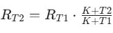
Non-linear Temperature Conversion:
Tap Changer (OLTC/DETC) Status:
DETC: De-energized tap changers can form oxide layers if left unmoved for long periods. Recommendation: Cycle the tap changer more than 5 times before measurement.
OLTC: The continuity of every tap position must be checked. A sudden increase in resistance at a specific tap usually indicates contact erosion or degradation of the transition resistors.
Structural Defects:
Strand Breakage: If some strands in a multi-strand winding are broken or if there is a cold solder joint in the leads, the effective cross-sectional area decreases, resulting in a stable but significantly higher resistance value.
Preparation and Discharge: After power-off, perform a three-phase short-circuit ground discharge for at least 5 minutes to eliminate residual charges from insulation layers and ground capacitance.
Equipment Selection: * Current Selection: The test current should not exceed 10% of the rated current to prevent resistance drift caused by winding heating.
Resolution: For low-voltage sides, the resolution must be better than 0.1mΩ.
Logical Judgment:
Phase-to-Phase Difference: For transformers above 1600kVA, the difference should be no more than 2% of the three-phase average.
Line-to-Line Difference: The difference should be no more than 1% of the three-phase average.
Historical Comparison: Compared with factory values or previous tests, the change should not exceed ±2%.
The essence of improving winding resistance test accuracy lies in: "Four-wire wiring is mandatory, contact polishing is essential, reading stability is required, and temperature conversion must be precise." Only by minimizing physical interference and standardizing the measurement process can the true health of the internal windings be accurately diagnosed through the data.
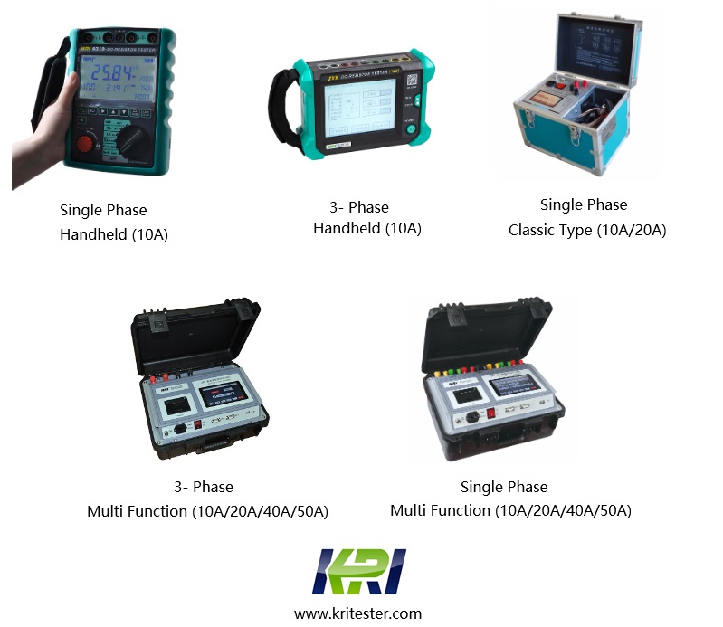
Kingrun Transformer Instrument Co.,Ltd.


Kingrun Series DC winding resistance testers