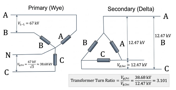
In electrical power systems, the Transformer Turn Ratio (TTR) refers to the ratio of the voltage between the high-voltage (HV) winding and the low-voltage (LV) winding, which is numerically equivalent to the ratio of their winding turns. Ratio testing is not only a mandatory item for factory inspection and commissioning tests but also a critical diagnostic tool in preventative maintenance. It helps identify inter-turn short circuits, verify the correct positioning of tap changers, and determine if transformers can operate in parallel. Even a minute measurement deviation can mask severe internal defects or lead to electromagnetic imbalance. Therefore, exploring the multi-dimensional factors affecting the accuracy of ratio testers and establishing a standardized measurement system is of profound significance for ensuring grid safety.
The measurement accuracy of an instrument is constrained by the physical limits of the signal processing chain and the underlying algorithmic logic.
Hardware Performance Specifications:
Reference Stability: The temperature drift coefficient of the internal reference source should be better than ±50 ppm/°C. In extreme outdoor temperature fluctuations (e.g., -10°C to 40°C), an uncompensated instrument can exhibit a gain drift of approximately ±0.25%.
Output Impedance: The signal source output impedance should be controlled below 50Ω to minimize waveform phase distortion caused by the distributed capacitance of the test leads.
Calibration and Algorithmic Quality:
Non-linear Error: Calibrating only at full scale can lead to accuracy degradation in low-ratio ranges (near 1:1). Periodic calibration must cover multiple range points.
Frequency Tracking: Without a Digital Phase-Locked Loop (DPLL), grid frequency fluctuations exceeding 0.1Hz will cause phase calculation errors, which translate directly into measurement errors for transformers with phase shifts (e.g., D/y11).
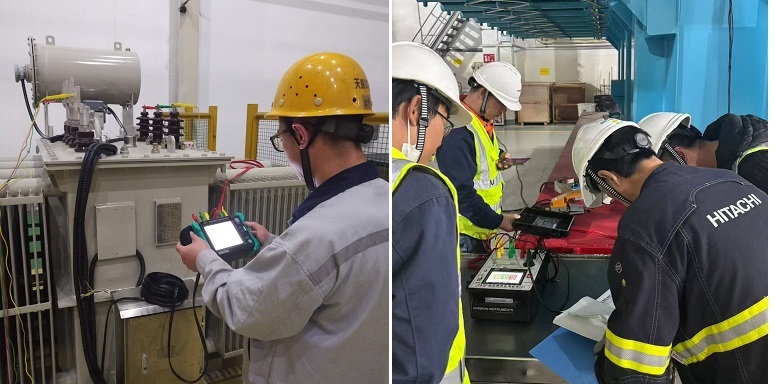
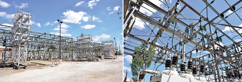
The complex electromagnetic environment at high-voltage sites is the primary cause of reading "instability" or "jitter."
Induced Voltage and Spatial Coupling:
In ultra-high voltage substations (e.g., 500kV), test leads act as antennas, coupling tens of mV of power-frequency interference. If the tester's input impedance is mismatched, interference signals superimpose directly onto the sampled measurement values.
Harmonic Pollution: Harmonics (2–9kHz) generated by nearby variable frequency drives (VFDs) or non-linear loads distort the sine wave, causing readings based on RMS algorithms to fluctuate by more than ±0.3%.
Grounding System Integrity:
Loop Currents: Multi-point grounding is strictly prohibited. It creates ground loop currents within the shield layer, generating 50Hz interference. The single-point grounding principle (grounding only at the instrument side) must be followed.
Equipotential Bonding: Ensure the instrument chassis ground and the transformer tank ground are at the same potential to prevent parasitic currents in the test circuit.
Statistically, 80% of field measurement anomalies stem from operational details.
Impact of Contact Resistance:
Voltage Drop Effect: If contact resistance reaches 0.5Ω due to aged or oxidized clamps, it produces a 0.5V drop at a 1A test current. This is fatal for LV-side signals and causes the calculated ratio to be significantly higher than the actual value.
Four-Wire Method (Kelvin Connection): For high-current or high-ratio tests, four-wire wiring must be used to separate the current loop from the voltage sampling loop, completely eliminating lead resistance errors.
Transformer State Management:
Residual Magnetism (Remanence): Residual magnetism following a DC resistance test causes excitation current waveform distortion when voltage is applied. AC demagnetization must be performed before measurement.
Tap Changer Position: Poor contact or an improperly seated tap changer introduces massive random contact resistance. It is recommended to operate the tap changer 3–5 times before measurement to clear the oxide film on the contacts.
Residual Charge Discharge: The transformer must be thoroughly discharged (especially after high-capacity DC testing). Otherwise, residual charges will not only interfere with readings but may also break down the instrument’s protection circuitry.
Sometimes, "errors" are actually reflections of internal faults or inherent physical characteristics of the transformer.
Winding and Core Defects:
Inter-turn Short Circuits: Ratio measurements typically appear slightly lower than the rated value (0.5%–2%), often accompanied by excessive DC resistance unbalance rates.
Core Saturation: If the test voltage is set too high (exceeding 10% of the rated excitation voltage), the core enters the saturation region, causing the ratio reading to be falsely low. The instrument's "Auto Voltage Selection" feature should be prioritized.
Temperature Effects and Excitation Current:
Winding resistance increases by approximately 0.4%/°C. Although the ratio is a voltage ratio, in transformers with heavy-load designs, temperature-induced changes in tap changer pressure can indirectly affect contact resistance.
Vector Group Mismatch: If the vector group (e.g., Y/d11 vs. Y/y0) is set incorrectly, the instrument’s phase correction algorithm will fail, resulting in a completely erroneous ratio.
Warm-up: The instrument must be warmed up for 20–30 minutes to allow the internal precision reference to reach thermal equilibrium at its rated drift specifications.
Standard Verification: Periodically verify the unit using a standard transformer of a known ratio (e.g., Class 0.05). If the deviation exceeds ±0.1%, focus on troubleshooting the cable shielding.
Interference Suppression Techniques:
In strong magnetic field areas, use twisted-pair test leads passed through a ferrite core to suppress common-mode interference.
Power the instrument via an isolation transformer or an online UPS to filter out grid spikes and noise.
Standardized Operation:
Take 3–5 consecutive readings for each tap position, discarding extremes to calculate the average.
Re-clamp the leads for a second comparison; if the deviation is >0.1%, it indicates unreliable contact.
Improving the accuracy of turn ratio testing relies on the principle: "Hardware is the foundation, anti-interference is the core, and standardized practice is the key." Only by creating a closed loop—from hardware selection and environmental control to standardized SOPs and periodic cross-verification—can measurement uncertainty be controlled within ±0.1%, providing the most reliable data support for transformer health assessment.
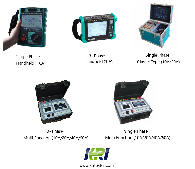
Kingrun Transformer Instrument Co.,Ltd.


Kingrun Series DC winding resistance testers