How to Accurately Test Transformer Turns Ratio?
1.Core Concept of Transformer Turns Ratio
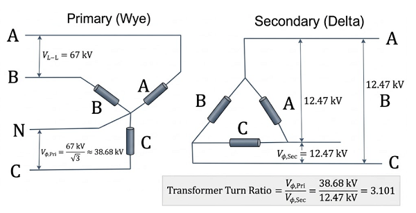
The transformer turns ratio, also referred to as the voltage ratio, represents the ratio of the number of turns between the primary and secondary windings. Under no-load conditions, this value is approximately equal to the ratio of the primary rated voltage to the secondary rated voltage, which can be expressed by the formula K = N₁ / N₂ ≈ U₁ₙ / U₂ₙ, where N₁ and N₂ denote the number of turns of the primary and secondary windings, U₁ₙ and U₂ₙ refer to the rated voltages of the primary and secondary sides, and K stands for the voltage or turns ratio. This parameter directly determines the accuracy of voltage transformation, and any deviation may lead to unqualified output voltage, overheating, circulating current, or maloperation of protective devices. It also verifies the correctness of winding turns and the matching of tap-changer positions, while effectively detecting hidden faults such as inter-turn short circuits, incorrect connections, and tap defects, making it indispensable for factory acceptance tests (FAT), site acceptance tests (SAT), as well as transformer installation, commissioning, maintenance, and fault diagnosis.
2.Purpose of Turns Ratio Testing
Turns ratio testing is performed to verify that the actual number of winding turns conforms to design values and that the tap-changer position corresponds to the indicated gear. It also serves to detect short-circuited turns, incorrect wiring, and poor connections, providing key data for factory and site acceptance testing. Furthermore, it forms an important basis for on-site installation, commissioning, routine maintenance, and fault diagnosis, ensuring that transformers operate with correct voltage transformation and stable electrical performance.
3.Preparations Before Turns Ratio Testing
All high-voltage and low-voltage power supplies must be disconnected and windings fully discharged before testing to avoid hazards from induced voltage. Test terminals should be cleaned to remove oxide layers and ensure reliable electrical contact. A turns ratio tester with an accuracy rating of at least 0.1% should be selected and preheated for approximately 10 minutes to minimize temperature drift. Transformer nameplate data must be reviewed carefully, the tap-changer should be set to the rated tap position, and any residual magnetism should be eliminated to prevent interference with measurement results.
4.Wiring and Operation Steps
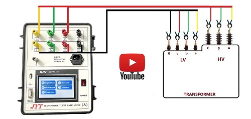
During wiring, the high-voltage output of the tester shall be connected to the primary winding of the transformer, while the low-voltage input shall be connected to the secondary winding, with strict attention paid to polarity consistency to avoid reverse connection errors. Short test leads or shielded cables are recommended to reduce electromagnetic interference, and three-phase transformers shall be wired correctly according to their vector group configuration, such as Yyn0 or Dyn11. During measurement, the tester shall be set to single-phase or three-phase mode according to the actual winding connection; a stable test voltage of no less than 1% of the rated voltage, preferably at least one-third of the rated voltage, shall be applied. Once readings stabilize, the turns ratio value shall be recorded, and each tap position shall be tested sequentially with two to three repeated measurements to obtain an average value, with ambient temperature and humidity recorded simultaneously for subsequent error analysis.
5.Key Accuracy Assurance Techniques
To ensure high measurement accuracy, modern high-precision testers typically use three-phase simultaneous measurement to automatically compensate for asymmetry errors caused by electromagnetic coupling between phases in three-phase transformers. Excessively high test voltage shall be avoided to prevent core saturation, which may distort excitation current and lead to inaccurate results. Correct configuration of the vector group is also critical, as an incorrect setting will cause significant ratio deviations even if the windings themselves are intact.
6.Judgment Standard & Fault Analysis
In accordance with IEC and relevant national standards, the allowable deviation for transformer turns ratio is generally within ±0.5%. Common abnormal test results include excessive ratio deviation, unstable readings, and three-phase asymmetry. Excessive deviation is usually caused by incorrect tap positions, inter-turn short circuits, or wiring errors; unstable readings often result from poor contact, residual magnetism, or external electromagnetic interference; and three-phase asymmetry typically indicates winding damage or tap-changer defects.
Summary
Precise turns ratio testing is essential for validating the voltage transformation performance and internal structural integrity of power transformers. Strict adherence to no-load test conditions, correct polarity, standard wiring practices, and repeated measurements across all tap positions ensures reliable and consistent test results. When combined with the DC winding resistance test, turns ratio testing enables comprehensive evaluation of tap-changer condition, inter-turn short circuits, and other hidden internal defects, thereby supporting the safe and stable operation of transformers and the entire power distribution system.
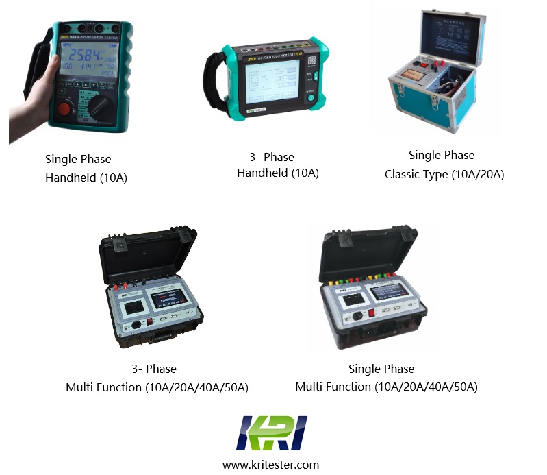
Kingrun Transformer Instrument Co.,Ltd.


Kingrun Series DC winding resistance testers