
As the core equipment of the power system, the operational reliability of the transformer is directly related to the security and stability of the power grid. Among the numerous parameters of a transformer, the Voltage Ratio (Turns Ratio) and DC Resistance are the two most fundamental and intuitive indicators. They are not only the first two items conducted during Factory Acceptance Tests (FAT) and Site Acceptance Tests (SAT), but also serve as the critical basis for installation, commissioning, maintenance, and fault diagnosis. The accuracy of these two parameters directly affects all subsequent transformer parameters and holds significant importance for evaluating performance and identifying latent hazards such as inter-turn short circuits and poor contact of the tap changer.
1. Transformer Voltage Ratio
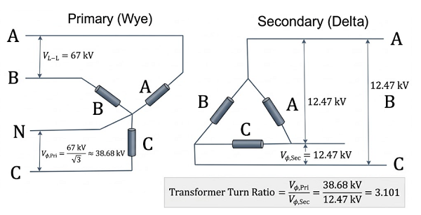
The transformer ratio is essentially the ratio of the number of turns between the primary and secondary windings. Under no-load conditions, it is approximately equal to the ratio of the primary rated voltage to the secondary rated voltage, expressed by the formula:
where N₁ and N₂ represent the turns of the primary and secondary windings respectively, and U₁ₙ and U₂ₙ are the corresponding rated voltages. Based on the magnitude of the ratio, transformers are classified into step-up, step-down, and isolation transformers. The accuracy of the ratio directly determines the precision of voltage transformation. When the ratio deviates from the design value, it may lead to unqualified output voltage or even trigger equipment overheating or protection maloperation due to excessive circulating currents. The core purpose of precise ratio measurement is to verify the correctness of the winding turns, ensure the indicated position of the tap changer corresponds to the actual connection, and determine the presence of faults such as inter-turn short circuits.
2. DC Resistance
DC resistance refers to the resistance value presented by the transformer winding when a direct current is applied, following Ohm’s Law (R = U/I). Although the transformer exhibits inductive characteristics during AC operation, the DC resistance reflects the winding material, cross-sectional area, contact resistance of connection points, and the quality of inter-turn welding. It also indicates whether the contacts of the tap changer are in good condition, whether there are broken strands in parallel branches, and serves as an auxiliary basis for judging winding deformation. Furthermore, the symmetry of the windings can be assessed through the three-phase resistance unbalance rate.
Pre-test Preparation: Ratio measurement should be conducted under no-load conditions. The excitation voltage is typically required to be no less than 1% of the rated voltage to ensure the core enters a normal excitation state and avoid errors caused by the non-linearity of magnetic permeability. For large transformers, the test voltage should not be excessively high to prevent core saturation from causing excitation current distortion.
Disconnect the power supply from both high and low-voltage sides and fully discharge the windings.
Clean the oxide layer from the test terminals to ensure good contact.
Select a ratio tester with an accuracy of no less than 0.1% and preheat for 10 minutes to avoid the impact of instrument temperature drift.
Record the nameplate parameters and verify the tap changer position to ensure it is at the rated tap. If residual magnetism exists, it must be eliminated by no-load operation before measurement.
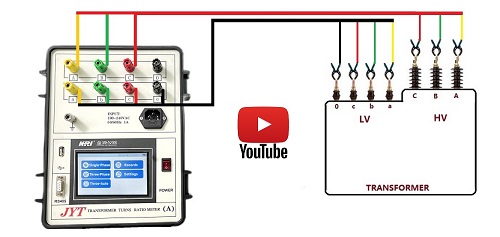
Wiring Operation: Connect the high-voltage end of the tester to the primary winding terminals and the low-voltage end to the secondary terminals. Strictly distinguish polarity (same-polarity ends) to avoid measurement deviations caused by reverse connection. Keep test leads as short as possible to reduce lead resistance, and use shielded cables if necessary to resist electromagnetic interference. For three-phase transformers, the three-phase voltage lines must be connected correctly according to the vector group (e.g., Yyn0, Dyn11). Incorrect wiring will lead to measurement failure or severe deviations due to phase differences, even if the ratio value itself is correct.
Measurement and Recording: Start the tester, select the corresponding measurement mode, and apply a stable test voltage (not less than 1/3 of the rated voltage of the energized side). Record the ratio value once the reading stabilizes. Measure each tap position of the tap changer individually, repeating 2-3 times per tap to take the average. Synchronously record ambient temperature and humidity for subsequent error analysis.
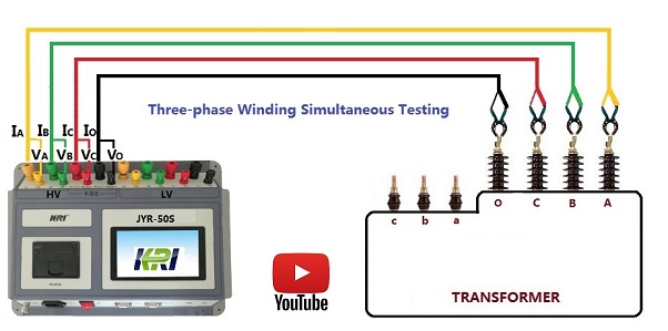
Accuracy Assurance: The most critical guarantee for accuracy lies in eliminating inter-phase interference. Due to electromagnetic coupling between the phases of a three-phase transformer, single-phase measurement is easily affected by other phases. Modern high-precision ratio testers mostly adopt simultaneous three-phase measurement technology, which can automatically compensate for errors caused by magnetic circuit asymmetry, thereby truly reflecting the actual ratio of each phase.
Pre-test Preparation: Cut off all power sources and discharge the windings for at least 5 minutes to prevent residual charges from damaging the instrument. Select appropriate equipment: a Wheatstone bridge for high-voltage windings (R > 1Ω) and a Kelvin (double) bridge for low-voltage windings (R < 1Ω), or use a high-precision automatic DC resistance tester. Record the ambient temperature for subsequent resistance temperature correction.
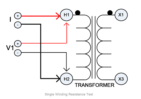
Wiring Operation: Adopt the "Four-terminal wiring method" (Kelvin sensing). Connect current terminals to the outer side of the winding and voltage terminals to the inner side to eliminate the influence of lead and contact resistance. For Star (Y) windings, measure phase or line resistance; for Delta (△) windings, either disconnect the connection points for measurement or convert line resistance to phase resistance through calculation to accurately judge the unbalance rate and avoid measurement errors. Ensure secure connections and clean the oxide layer of the terminals.
Measurement and Recording: Apply a constant DC current. The charging current should neither be too small (unable to overcome residual magnetism, causing reading drift) nor too large (causing winding heating, which changes resistance). Typically, 1%-10% of the rated current is selected, not exceeding 20A.
Record the value after the winding inductance charging is complete and the reading is stable.
Measure three-phase windings one by one and calculate the unbalance rate: δ=( Rmax-Rmin ) / Ravg×100%.
For large three-phase five-column transformers where low-voltage winding charging is extremely slow, the "Magnetic Assist Method" (Boost Method)—connecting high and low-voltage windings in series to apply co-directional magnetic flux—can reduce charging time from hours to minutes, significantly reducing errors from temperature drift.
Temperature Correction: Winding resistance has a linear relationship with temperature. For copper windings, resistance increases by approximately 0.4% for every 1°C rise. Therefore, the winding temperature must be accurately recorded, and all measured values must be converted to a reference temperature (usually 75°C or 20°C). For transformers that have just stopped running, the oil temperature and actual winding temperature may differ; sufficient standing time is required to equalize the temperature.
Demagnetization Treatment: Residual magnetism in the core prolongs the stabilization time of the test current and introduces measurement noise. Before each measurement, especially after switching tap changers, residual magnetism should be eliminated through reverse current charging/discharging or the instrument's built-in demagnetization program to reset the core's magnetic state to zero.
Instrument Requirements: The ratio tester accuracy should be ≥ 0.1%, and the DC resistance tester resolution should be ≥ 1μΩ. Periodically calibrate instruments using standard transformers and standard resistors (e.g., quarterly) to eliminate systemic errors.
Environmental Control: Maintain stable ambient temperatures (15-25°C). Stay away from strong electromagnetic interference sources like high-voltage equipment or frequency converters; use shielded leads if necessary. Use test leads with large cross-sections and low resistance, and shorten wiring length to minimize contact resistance.
Operational Stabilization: Thoroughly discharge the transformer before measurement. Ensure correct polarity for ratio tests and use the four-terminal method for DC resistance. After switching the tap changer, wait 3-5 minutes before measuring to ensure the contacts are stable. Repeat measurements at each point and take the average to reduce random errors.
Data Analysis: After measurement, correct DC resistance based on ambient temperature using the specific formulas for copper or aluminum windings. Calculate ratio deviations; if they exceed ±0.5%, investigate for wiring errors, winding faults, or tap changer issues. Three-phase DC resistance unbalance must comply with IEC 60076-1 requirements (e.g., ≤ 2% for units above 1600kVA).
Overcoming Inductive Effects: The greatest challenge in precise DC resistance measurement is the inductance effect. Due to the massive inductance of transformer windings, current does not reach a steady state immediately but rises exponentially. Readings taken before stabilization will be erroneously high. Therefore, modern precision measurements utilize constant current sources combined with high-speed digital sampling or demagnetization techniques to ensure readings are taken only after the magnetic flux has stabilized.
Although the measurement of ratio and DC resistance are routine tests, their precision directly affects the judgment of the transformer's condition. In practice, the results of both often require joint analysis. For example, poor contact in a tap changer will not only cause the DC resistance to exceed limits but may also cause fluctuations in the ratio measurement due to the non-linearity of the contact resistance. Similarly, an inter-turn short circuit will cause a significant drop in DC resistance and cause the ratio to deviate from the standard value.
To achieve the highest precision, one must also note: First, instrument traceability should ensure accuracy is better than 1/3 of the allowed error of the tested equipment. Second, test current selection must balance thermal effects and sensitivity; for large transformers, a current >10A is preferred to reduce dispersion. Third, test records must include complete metadata (ambient/winding temperature, tap position) to provide a basis for longitudinal historical comparison.
Kingrun Transformer Instrument Co.,Ltd.


More Transformer Testers from Kingrun


