The losses in a transformer primarily include core losses and copper losses, along with some additional losses. Core losses occur in the core and are mainly comprised of hysteresis losses and eddy current losses. Hysteresis losses arise from the energy loss due to changes in magnetization direction under alternating magnetic fields, while eddy current losses result from induced currents caused by the alternating magnetic field, leading to heat generation. Copper losses occur in the windings and are due to the resistive losses when current flows through the windings, also known as resistive losses. This loss is proportional to the square of the current, meaning that copper losses increase with higher loads. Additional losses include stray losses and mechanical losses; stray losses arise from leakage magnetic flux, while mechanical losses are associated with internal vibrations and noise. Load losses are related to the load level, with copper losses increasing as the load rises. Reducing these losses helps improve the efficiency of the transformer.

1. Calculation formula of transformer loss
(1) Active power loss: δ P = P0+KTβ2PK
(2) Reactive power loss:δ Q = Q0+KTβ2QK
(3) COMPREHENSIVE POWER LOSS: δ PZ = δ P+KQ δ Q
Q0≈I0%SN,QK≈UK%SN
Q0——No-load reactive power loss (LEFT)
P0 – No-load loss (kW)
PK——(kW)
SN – Rated capacity of transformer (kVA)
I0 % – the percentage of the transformer's no-load current.
UK %——Percentage of short-circuit voltage
β – Average load factor
KT – load fluctuation loss factor
QK——Rated load leakage power (KVAR)
KQ -- Economic equivalent of reactive power (kW/kvar)
2. Selection conditions of each parameter are as follows:
(1) KT = 1.05
(2) When the minimum load is taken from the 6kV~10kV step-down transformer of the city power grid and the industrial enterprise power grid, its reactive power equivalent KQ=0.1kW/kvar;
(3) The average load coefficient of transformer, the desirable β = 20% for agricultural transformers, and the desirable β=75% for industrial enterprises, which are implemented in three shifts;
(4) Transformer operating hours T=8760h, maximum load loss hours: T=5500h;
(5)No-load loss of transformer P0、Rated load loss PK、I0%、UK%
Second, the characteristics of transformer loss
P0 - no-load loss, mainly iron loss, including hysteresis loss and eddy current loss;
The hysteresis loss is proportional to the frequency and to the two squares of the hysteresis coefficient of the maximum magnetic flux density.
The eddy current loss is proportional to the product of frequency, maximum magnetic flux density, and thickness of the silicon steel sheet.
PC – Load loss, which is mainly the loss of load current through the resistance in the winding, is generally known as copper loss. Its magnitude varies with the load current and is proportional to the square of the load current (expressed as a standard coil temperature conversion value).
The load loss is also affected by the temperature of the transformer, and the flux leakage caused by the load current can produce eddy current losses in the windings and stray losses in the metal parts outside the windings.
Total transformer loss δ P=P0+PC transformer loss ratio=PC/P0
Transformer efficiency = PZ/(PZ+δP), expressed as a percentage, PZ is the output power on the secondary side of the transformer.
3. Calculation of variable loss of electricity
The power loss of a transformer includes iron loss and copper loss. Iron loss is related to running time, and copper loss is related to load size. Therefore, the loss of electricity should be calculated separately.
1. Calculation of iron loss power: iron loss power of different types and capacities, the calculation formula is: iron loss power (KWH) = no-load loss (kW) × power supply time (hours)
2. Calculation of copper loss: when the load rate is 40% or below, the electricity consumption of the whole month (to meter reading) is 2%
3. Calculation formula: copper loss (KWH) = monthly electricity consumption (KWH) ×2%
4. Calculation of no-load loss, load loss and impedance voltage
No-load loss: When the secondary winding of the transformer is open, and the rated voltage of the rated frequency sine waveform is applied to the primary winding, the active power consumed is called no-load loss. The algorithm is as follows: no-load loss = no-load loss process coefficient × unit loss × core.
Load loss: When the secondary winding of the transformer is short-circuited (steady-state), the active power consumed by the rated current of the primary winding is called the load loss.
The algorithm is as follows: load loss = resistance loss of the largest pair of windings + additional loss
Additional loss = eddy current loss of winding + cyclic loss of parallel winding line + stray loss + lead loss
Impedance voltage: When the secondary winding of the transformer is short-circuited (steady-state), the primary winding flows through the rated current, and the applied voltage is called the impedance voltage Uz. Generally, Uz is expressed as a percentage of the rated voltage, that is, Uz = (Uz/U1n)*100%
Rotation:u=4.44* F *B*At,V
JYW6100: Transformer No-load and Load Characteristics Tester (for transformer core loss, coil loss tester,power factor). Widely used in transformer,amorphous alloy transformer, generator, fan motor industries.
")
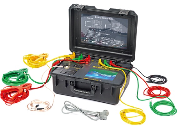

Kingrun Transformer Instrument Co.,Ltd.


More Transformer Testers from Kingrun