How to Accurately Measure Transformer No-Load Loss and No-Load Current?
1. Purpose and Significance of No-Load Testing
The complete excitation characteristics of a transformer are determined through no-load testing. The purpose of this test is to measure the transformer's no-load loss and no-load current, verify whether the transformer's core design and manufacturing processes meet the required standards and technical conditions, and check for core defects such as localized insulation failures. No-load loss is primarily caused by the hysteresis loss of electrical silicon steel sheets, while normal transformer additional losses can generally be ignored.
2. Test Setup and Voltage Application
In a transformer no-load test, a sinusoidal waveform voltage at rated frequency and rated voltage is typically applied to the winding with the lower voltage (e.g., the low-voltage winding), while other windings are left open-circuited.
If the winding with the applied voltage has taps, the tap changer should be set to its principal tap position. If the test object includes an open delta connection winding, it should be closed. Connections at ground potential and the transformer tank should be properly grounded during the test.
3. Instrumentation and Power Measurement Method
Special attention must be given to the polarity of voltage transformers and current transformers in the test wiring. For three-phase power measurement, the algebraic sum of two wattmeters should be used. Voltage and current transformers used in no-load tests should have an accuracy of at least 0.1 class, while instruments should have an accuracy of no less than 0.5 class. Power measurements should use wattmeters with a power factor (COSφ) below 0.2.
In field testing, the two-wattmeter method is commonly used, which involves two voltage transformers and two current transformers.
4. Voltage Unbalance and Waveform Distortion Handling
When the voltage unbalance symmetry of the tested transformer is less than 2%, the average value of the three line voltages or the line voltage between phases a and c can be used as the reference voltage for applying voltage and measuring no-load data. If the voltage unbalance is greater than 2% but less than 5%, voltages between phases a-b, b-c, and c-a can be applied separately. The test data is then averaged across three trials. When there is waveform distortion, such that the average voltage and the effective voltage differ on the voltmeter readings, the average voltage should be used to calculate voltage \( U \), no-load loss \( P_m \), no-load current \( I \), and effective voltage \( U \).
5. Single-Phase Testing and Interpretation for Three-Phase Transformers
For three-phase transformers, single-phase testing methods are used for no-load testing. Fault locations can be identified through such tests.
If the transformer's loss is significantly higher than similar transformers of the same type, the magnetic circuit may be problematic, and a single-phase no-load test should also be conducted. For transformers with a three-limb core structure, the current and loss from single-phase no-load tests can be converted to three-phase test results. However, for transformers with a five-limb core structure, single-phase test results cannot be converted to three-phase results and can only be compared with the results of transformers of the same model, capacity, and structure. Low-voltage no-load measurements for transformers also adopt single-phase measurement methods.
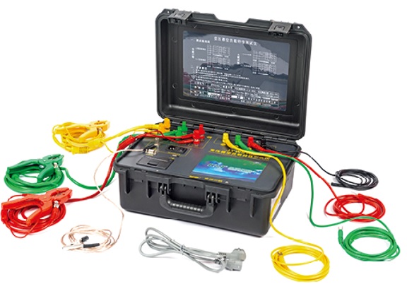
Transformer No-loads and On-loads Power Factor Tester
JYW6100

Kingrun Transformer Instrument Co.,Ltd.


More Transformer Testers from Kingrun


