
Abstract: Correctly selecting the transformation ratio for Current Transformers (CT) and Voltage Transformers (PT) is fundamental to ensuring the accuracy of electrical measurements and the reliability of protective relaying in power systems. This guide will detail the standardized principles for ratio selection, based on the International Electrotechnical Commission (IEC 61869 series) and industry standards, differentiating between requirements for measuring and protection-class instrument transformers.
The CT transformation ratio Ki is defined as the ratio of the rated primary current I1n to the rated secondary current I2n (Ki= I1n/ I2n)=
9). Internationally, the rated secondary current I2n is typically standardized at 5 A or 1 A.
The selection of I1n must balance the requirements for thermal stability and measurement accuracy.
The CT's rated primary current I1n must be greater than or equal to the maximum continuous operating current Imax expected in the circuit to ensure the long-term temperature rise and stability of the CT winding.
Design Rule: Select a standardized value for I1n that is slightly higher than Imax .
Engineering Practice: It is common to select I1n to be about 1.2 to 1.5 times Imax to provide a safety margin.
To ensure measurement accuracy, the minimum load current Imin must fall within the CT's specified accuracy operating range.
Requirement: Metering CTs (e.g., Accuracy Class 0.2 S) must maintain their accuracy down to a low limit, such as 1% or 5% of the rated current I1n. Selecting an I1n that is excessively large compared to Imax will cause the secondary current I2 to be very small during light load conditions, potentially dropping below the CT's accuracy limit and leading to increased metering errors.
In addition to the basic principles, protection-class CTs must be able to perform reliably under fault conditions.
Accuracy Limit Factor (ALF) / Saturation: Protection CTs are primarily concerned with their saturation characteristics during a fault. It must be ensured that the Accuracy Limit Current IALF = ALF x I1n covers the system's maximum possible short-circuit current Iscmax. This prevents severe CT saturation during a fault, ensuring the protective relaying equipment receives an accurate current signal for reliable operation.
| Risk Scenario | Consequence Analysis | Standard Practice |
|
Ratio Selected Too Small (I1n < Imax) |
High Risk. Leads to chronic CT overheating and insulation degradation. Under fault conditions, severe saturation occurs, potentially causing protection failure to trip (refusal) or false tripping (misoperation). |
Strictly adhere to the I1n ≥ Imax principle. |
|
Ratio Selected Too Large ((I1n > Imax) |
Causes the light-load current Imin to fall outside the CT's optimal accuracy range, increasing metering errors. May also reduce the sensitivity of protective relays. |
Ideally, maintain Imax within the 70% ~ 90% range of I1n |
The PT transformation ratio Ku is defined as the ratio of the rated primary voltage U1n to the rated secondary voltage U2n (Ku = U1n / U2n).
U1n must strictly match the rated system voltage Usystem at the connection point and the PT's wiring configuration.
Phase-to-Ground Connection: Primarily used in high-voltage systems with directly grounded neutrals (e.g., 110 kV and above).
Phase-to-Phase Connection: Primarily used in medium-to-low voltage systems with ungrounded or Petersen coil grounded neutrals (e.g., 6 kV, 10 kV).
The rated secondary voltage U2n is typically a standardized value to be compatible with secondary equipment.
| Application | Winding Type | Rated Secondary Voltage U2n |
| Measurement & Protection (Main Winding) | Connected Phase-to-Ground | 100 /√3 V |
| Measurement & Protection (Main Winding) | Connected Phase-to-Phase | 100 /√3 V |
| Ground Fault Protection (Auxiliary Winding) | Connected in Open-Delta for Zero-Sequence Voltage 3U0 | 100 /√3 V |
The ratio Ku is a dimensionless number, while the PT rating is typically specified as U1n / U2n.
Example: 110 kV System (Phase-to-Ground Connection)
Rated System Voltage Usystem = 110 kV
PT Primary Voltage U1n = 110 kV/ √3
PT Secondary Voltage U2n = 110 kV/ √3
Calculation of Ratio Ku:

The PT specification would be indicated as: 110000 / √3 / 100 / √3/ 100 V (referencing the main and auxiliary windings).(referencing the main and auxiliary windings).
| Instrument Type | Core Selection Criterion | Key Principles | Applicable Standards |
| CT | Primary Current I1n |
1. Satisfy Max Load (I1n ≥ Imax); 2. Ensure Min Current is within Accuracy Range. |
IEC 61869-2 |
| PT | Primary Voltage U1n |
1. Strictly match System Voltage Usystem; 2. Match Wiring (U/√3 for Phase-to-Ground or U for Phase-to-Phase). |
IEC 61869-3 |
Recommendation: In engineering design, one should always refer to the latest national and international standards (such as IEC 61869 series) and select the accuracy class and rated ratio based on the specific application (measurement/metering or protection) of the CT and PT.
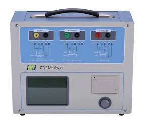
CT& PT Analyzer JYH-C from Kingrun

The 5 Most Popular transformer turn ratio testers in the World
What is the Difference between "Ratio" and "Turn Ratio" in a Transformer Testing?
How to Choose the Right Turns Ratio of CT/PT?
Why is it so Important to Test Transformer Turn Ratio?
What are the Reasons for Abnormal Voltage Output of Power Transformers?
Kingrun Transformer Instrument Co.,Ltd.


