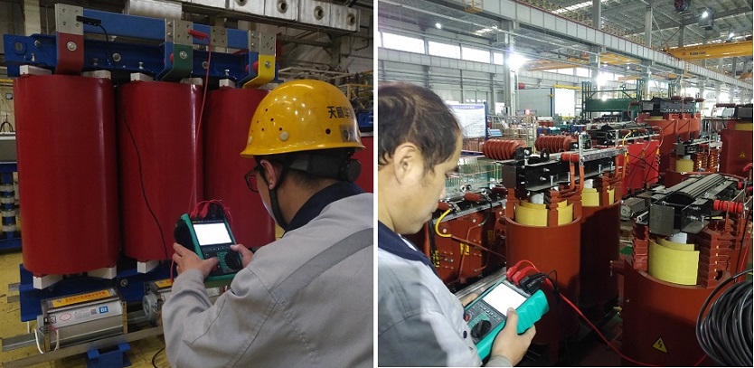
Purpose of Transformer Winding DC Resistance Measurement:
· To check the quality of winding solder joints and detect inter-turn short circuits.
· To identify conductor strand breakage or disconnection issues in windings or leads.
· To assess the contact quality of tap changer positions and verify the consistency between the actual tap position and its indicator.
· To detect strand breakage in parallel windings.

Testing Frequency of Winding DC Resistance Measurement:
1. During commissioning.
2. After major overhauls.
3. Every 1-3 years.
4. After tap position changes in no-load tap-changing transformers.
5. After the tap changer of load-tap-changing transformers is serviced (measure at all tap positions).
6. As needed.
Principle of Winding DC Resistance Measurement:
When time t=0t = 0t=0, I=0I = 0I=0, and as t→∞t \to \inftyt→∞, I=En/RI = E_n / RI=En/R, reaching a steady state.
Due to the high inductance and low resistance of transformer windings, the inductance can reach hundreds of henries, resulting in a large time constant. For high-voltage, large-capacity transformers, achieving stable resistance measurements can take minutes, tens of minutes, or even hours. Using appropriate measurement methods and equipment is crucial for ensuring accuracy.
To reduce the total test time during DC resistance measurements, two effective strategies can be employed: decreasing the inductance (L) of the transformer winding or increasing the series resistance (R) in the measurement circuit. Reducing the inductance can be achieved by increasing the measurement current, which saturates the transformer core and lowers its magnetic permeability. Increasing the series resistance involves adding an external resistor approximately 4–6 times larger than the winding’s measured resistance. Additionally, the applied measurement voltage should be sufficiently high to prevent excessively low currents, which could compromise measurement sensitivity. By carefully balancing these parameters, technicians can achieve faster, more accurate, and reliable DC resistance measurements without sacrificing precision.

Analysis and Judgment of Winding DC Resistance Measurement Results:
1. For transformers above 1.6 MVA, the resistance differences between windings should not exceed 2% of the three-phase average value. For windings without a neutral point, the phase-to-phase difference should not exceed 1% of the three-phase average value. (Unbalance rate = (maximum measured value - minimum measured value) / average value of the three phases).
2. For transformers of 1.6 MVA and below, the phase-to-phase difference should generally not exceed 4% of the three-phase average, and the line-to-line difference should not exceed 2%.
3. The resistance of each phase winding, compared with historical results under the same temperature and location, should not exhibit significant differences. Deviations greater than 2% are unacceptable, and differences exceeding 1% warrant attention.
Other Related Articles:
The Most Complete Transformer Vector Group Collection with Winding Connection Diagrams
How Important is Transformer DC Winding Resistance?
Top 6 transformer winding resistance testers Worldwide (Including Prices)
How should Winding Resistance be Tested Differently on CT and PT?
What is the Difference between DC Resistance and Insulation Resistance and How to Test Them?
8 Tips to Improve the Accuracy of DC Resistance Measurement
Why is the Tested Winding Resistance Always Inaccurate? You May Have Overlooked These 6 Key Points
Kingrun Transformer Instrument Co.,Ltd.


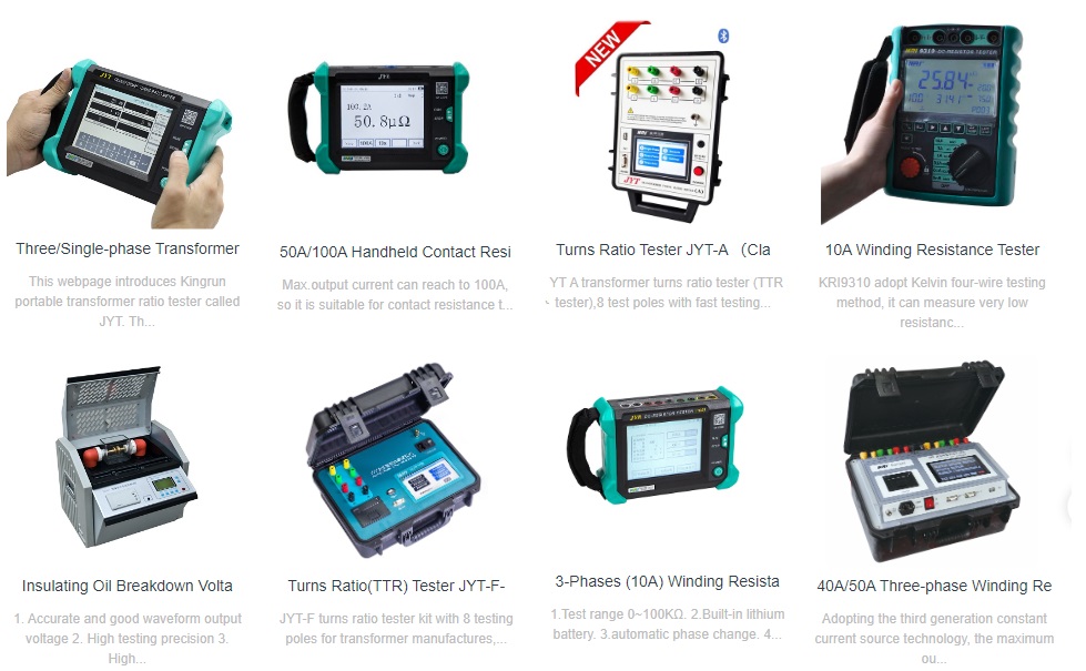
More Transformer Testers from Kingrun
