A certain transformer exhibited an unbalance rate of 2.17% in the direct current resistance between the 10kV low voltage lines, exceeding the national standard value of 1% by more than double. After identifying the defect, all connections between the leads and the conductor poles were tightened, and several follow-up tests were conducted, but the defect persisted.
Chromatographic analysis revealed that the concentration of C2H2 in the transformer exceeded the limit, rising from 0.2 µL/L to 7.23 µL/L, indicating the presence of a discharge fault. However, according to the maintenance records of the main transformer, it was noted that prior to the observed change in C2H2, the transformer had undergone two soldering repairs without degassing treatment. The levels of other gases were generally normal. An analysis using the three-ratio method indicated no signs of overheating, and historical pre-test data showed that all other parameters were normal except for the excessive direct current resistance unbalance.
Analysis of DC Resistance Imbalance
Upon analysis, it was determined that the resistance value of phase C was relatively high, raising suspicions of a possible broken strand. After consulting the manufacturer, it was confirmed that this winding consists of 24 strands. Calculating based on this, if one strand were to break, the resultant error would align with the actual measurement error, leading to the conclusion that there is an internal broken strand in phase C. A visual inspection of the delta connection terminals and a multimeter measurement verified the presence of a broken strand in phase C.
Diagnosis of On-Load Tap Changer Faults
In a certain transformer, the direct current resistance was unbalanced on the 110kV side, with significant discrepancies in the resistance values between phase C and its taps. The direct current resistance variations between taps for phases A and B ranged from 10 to 11.7 µΩ, while for phase C, the variations ranged from 4.9 to 6.4 µΩ and 14.1 to 16.4 µΩ, suggesting abnormalities in the phase C circuit.
Analyzing the direct current resistance data for C0 (the circuit from terminal C to neutral point 0), it was determined that the likelihood of defects within the winding itself was low. The possibility of defects in the polarity switch and selector switch of the on-load tap changer was also deemed minimal, suggesting that the fault might lie within the switching mechanism. An inspection of the switch housing revealed that a fixed point of the polarity switch to the selector switch had a broken screw, resulting in increased contact resistance at the neutral point and leading to irregular direct current resistance readings.
Diagnosis of No-Load Tap Changer Faults
During the commissioning and acceptance tests of a transformer renovated by a power equipment manufacturer, it was discovered that the direct current resistance data for the no-load tap changers of the A, B, and C phases were disordered and lacked consistency, with the measured direct current resistance values not corresponding to the tap positions.
It was noted that the switch positions of all three phases did not match the indicated positions. After conducting a visual inspection and confirming the absence of an empty position, readjusting and reassembling the switches restored normal function.
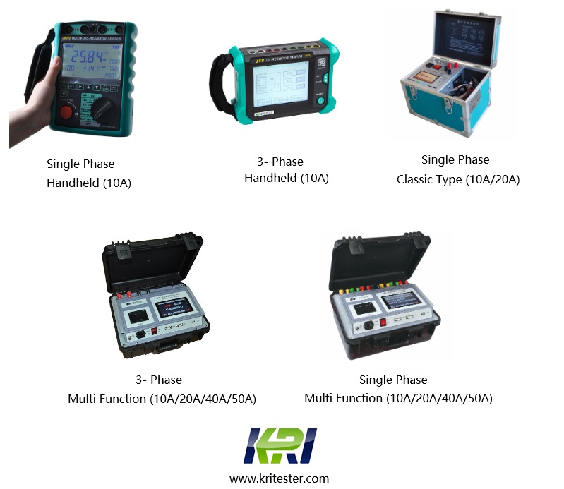
JYR-10S/20S/40S/50S adopts third-generation constant current source technology, with a maximum output current of 50A (40A), a range of 0Ω to 20kΩ, and an output voltage of up to 24V. It features a built-in channel conversion matrix. With the JYR40S/50S, various tests on power transformers can be performed without rewiring. The instrument can complete three-phase simultaneous tests, phase-by-phase tests, magnetic assistance tests, and single-phase DC winding resistance tests.
High Voltage YN Three-Phase Simultaneous Testing: Includes compensation testing (including O phase resistance) and phase-by-phase testing functions. Features automatic magnetization assistance for YND11 transformers, high and low voltage D/Y three-phase phase selection measurement, and automatic calculation of the three-phase resistance balance rate for high voltage.
Other Related Articles:
The Most Complete Transformer Vector Group Collection with Winding Connection Diagrams
How Important is Transformer DC Winding Resistance?
Top 6 transformer winding resistance testers Worldwide (Including Prices)
How should Winding Resistance be Tested Differently on CT and PT?
What is the Difference between DC Resistance and Insulation Resistance and How to Test Them?
8 Tips to Improve the Accuracy of DC Resistance Measurement
Why is the Tested Winding Resistance Always Inaccurate? You May Have Overlooked These 6 Key Points
Kingrun Series DC winding resistance testers

Kingrun Transformer Instrument Co.,Ltd.


More Transformer Testers from Kingrun
