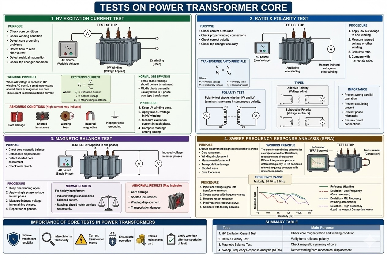
The core is the main component of the magnetic circuit in a power transformer. The health of the core and its associated circuits directly determines the operating efficiency and safety of the transformer. The following section provides a detailed analysis of the four core testing items:
The fundamental mathematical relationship is expressed as:
Ie= V/Xm
Ie= Excitation current
V= Applied voltage
Xm= Magnetizing reactance

Ratio Test:Verifies whether the turns ratio between the high-voltage and low-voltage windings complies with the design specification. The formula is:
V1/ V2= N1/ N2
(where V represents voltage and N represents the number of winding turns).
Polarity Test:Determines the relative direction of the induced electromotive force between the HV and LV terminals at any given instant (identifying dot polarity). It is classified intosubtractive polarity(industry standard) andadditive polarity.
Commissioning & Post-Overhaul:A mandatory test performed before putting a new or repaired transformer into service to ensure error-free winding connections.
Tap Changer Alternation:Validating the contact status and step accuracy at every position after changing the tap changer position.
Prior to Parallel Operation:Checking the ratio and polarity/vector group before connecting two or more transformers in parallel.Parallel operation of transformers with incorrect polarity or vector groups is strictly prohibited.
This test effectively prevents severephase-to-phase short circuits, massive circulating currents, and phase mismatches, thereby ensuring safe parallel operations.
The magnetic balance test is a qualitative diagnostic method unique to three-phase transformers. By applying a low AC voltage to one phase winding, it uses the flux distribution of the core to evaluate the induced voltages across the other two phases. This test is highly sensitive to the integrity of the magnetic circuit and subtle changes in the symmetry of the core geometry.
Post-Transportation Inspection:Performed after long-distance transit or severe vibration to evaluate if the core has shifted or loosened.
Post-Short-Circuit Shock:Performed after the transformer experiences a severe external through-fault current to inspect for mechanical deformation of the core and windings.
Normal Results:For a healthy transformer, the induced voltages should follow a strictly symmetrical magnetic distribution pattern (e.g., when exciting Phase A, Phases B and C split the voltage proportional to their magnetic path lengths) and should closely match factory or historical data.
Abnormal Results (Unbalance):Distorted or highly unbalanced readings typically indicate local core damage, shorted laminations, winding displacement, or structural damage sustained during transportation.
Every transformer winding can be modeled as a complex electrical network consisting of resistance (R), inductance (L), and distributed capacitance (C). Within this network, the core acts as the dominant inductive element.
SFRA works by injecting a low-voltage swept frequency signal (ranging from 20 Hz to 2 MHz) into the winding and measuring its frequency response curve (the network's "fingerprint"). Any core movement, looseness, or winding displacement alters these R-L-C parameters, causing the frequency response curve to deviate or distort from its baseline.
After Extreme Fault Currents:Diagnosing winding deformation after the transformer survives a severe near-zone short-circuit fault.
Before and After Heavy Transportation:Serving as a fingerprint comparison, this is themost authoritative methodto determine if a transformer sustained internal mechanical damage during transit.
Advanced Diagnostics:Troubleshooting mechanical anomalies that conventional tests (such as DC resistance or turns ratio) cannot pinpoint.
Comprehensive core testing provides critical benefits throughout the life cycle of a power transformer:
1.Improves Operational Reliability:Keeps track of core degradation trends under long-term operational stress.
2.Early Fault Warning:Captures minor anomalies (e.g., multi-point core grounding, inter-laminar shorts) before they escalate into catastrophic failures.
3.Closed-Loop Quality Management:Enables full life-cycle comparative analysis across manufacturing, transit, installation, and major overhauls, significantly reducing maintenance costs and ensuring grid stability.
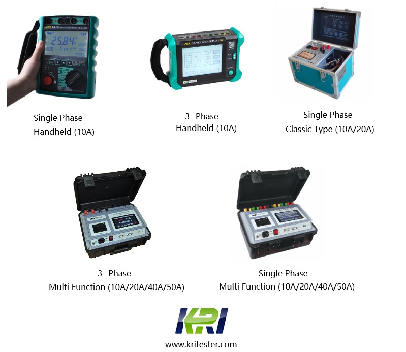
Kingrun Transformer Instrument Co.,Ltd.


Kingrun Series DC winding resistance testers