In the field of transformer diagnostics, the "one-size-fits-all" approach to selecting test current is a common but dangerous fallacy. While modern automatic DC resistance testers offer high precision, their accuracy is entirely dependent on the operator’s ability to balance Signal-to-Noise Ratio (SNR) against Thermal Drift. Utilizing a fixed current for both High-Voltage (HV) and Low-Voltage (LV) windings—or blindly selecting the maximum available current—sacrifices data integrity and risks equipment damage.
Using a constant current (e.g., 5A or 10A) across all windings introduces three primary failure modes:
SNR Deficiency in LV Windings: LV windings often exhibit resistance in the micro-ohm (μΩ) or low milli-ohm (mΩ) range. An insufficient test current produces a voltage drop so minute that it is easily masked by electromagnetic interference (EMI) or thermal EMFs. This leads to erratic readings and poor repeatability.
Thermal Instability in HV Windings: HV windings consist of thinner conductors with higher resistance (several Ohms to tens of Ohms). High currents in these circuits generate significant Joule heating (P = I2R). Since copper's resistance increases by approximately 0.4% per 1℃, the resistance value will "drift" upward during the test, rendering the measurement non-compliant with standard reference temperature folding.
The "Masking" of Tap Changer Defects: A fixed current may either be too low to "wet" the contacts of an On-Load Tap Changer (OLTC), failing to detect carbonization, or too high, temporarily bridging a poor contact through localized heating, thus hiding a critical defect.
According to international standards, the selection of test current must be governed by the transformer's rated current and the saturation characteristics of the core.
A fundamental industry guideline is that the test current should be sufficiently high to overcome core remanence but never exceed 15% of the winding's rated current. Exceeding this threshold causes rapid temperature elevation of the winding, leading to significant measurement error.
Transformer windings are massive inductors. The time required to reach a stable reading (t = L / R) is dependent on the current's ability to saturate the core.
Low Resistance (LV): Requires high current to generate a measurable voltage drop.
High Resistance (HV): Requires lower current to prevent voltage compliance issues in the tester and to maintain thermal equilibrium.
Based on global testing conventions, the following matrix should be used as the primary reference for current selection:
| Winding Category | Typical Resistance Range | Recommended Current | Rationale |
| LV Windings (Large Power) | < 100mΩ | 10A – 40A | High current is required to maximize SNR and saturate the core effectively. |
| Distribution LV / 10kV HV | 100mΩ – 2Ω | 1A – 5A | Balances stabilization speed with thermal safety. |
| 35kV – 110kV HV Windings | 2Ω – 20mΩ | 0.5A – 1A | Prevents I2R heating while ensuring steady-state DC. |
| Instrument/Large HV/Neutral | > 20Ω | ≤100mA | Avoids tester voltage saturation and preserves winding integrity. |
Always begin testing with a medium-range current (e.g., 1A or 5A).
If the reading stabilizes in under 30 seconds with no drift, the current is optimal.
If the reading fluctuates or "hunts," increase the current to improve SNR.
If the reading trends upward continuously, decrease the current to mitigate thermal drift.
When performing measurements on a tap changer, the same current must be used for all positions. This ensures that the results are comparable and that any variance in resistance is attributable to the contact condition or winding length, rather than a change in the tester's burden.
For large GSU (Generator Step-Up) transformers where the LV winding charging time is prohibitive, use the Magnetic Assist method (energizing HV and LV in series). However, once the core is saturated, revert to the recommended current levels for the final precision reading to ensure the 15% thermal rule is maintained.
In professional transformer testing, the objective is Saturation without Heat. High current is a tool for resolution, not a goal in itself.
"High for Low, Low for High; Stable, Cool, and Test to Die."
(High current for low resistance, low current for high resistance; ensure stability without heating, and test to the reference standard.)
By adhering to these impedance-matching principles, testing personnel can guarantee that the reported DC resistance reflects the true physical state of the transformer, rather than an artifact of improper test parameters.
For a specific recommendation, please provide the transformer's Power Rating (kVA/MVA), Voltage Ratio, and Vector Group.
Kingrun Transformer Instrument Co.,Ltd.


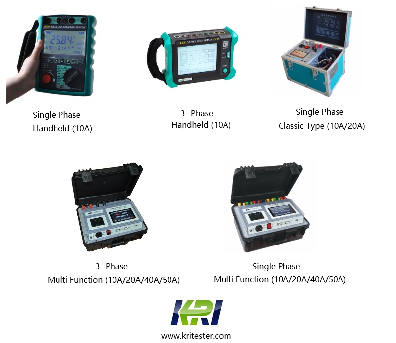
Kingrun Series DC winding resistance testers