
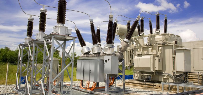
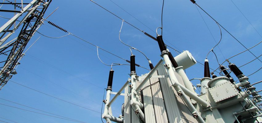
In the operation of power transformation and distribution, transformers are indispensable, and it is very necessary to be familiar with and master the basic common sense of transformers.
1. What is the transformer?
In the AC circuit, the device that increases or decreases the voltage is called a transformer. The transformer can convert any value of voltage into the voltage value we need with the same frequency to meet the transmission, distribution and use requirements of electric energy. For example, the electricity from a power plant has a low voltage level, and the voltage must be increased to be transported to a distant power consumption area. The power consumption area must be reduced to a suitable voltage level to supply power equipment and daily electricity. Equipment.
2. How does the transformer transform the voltage?
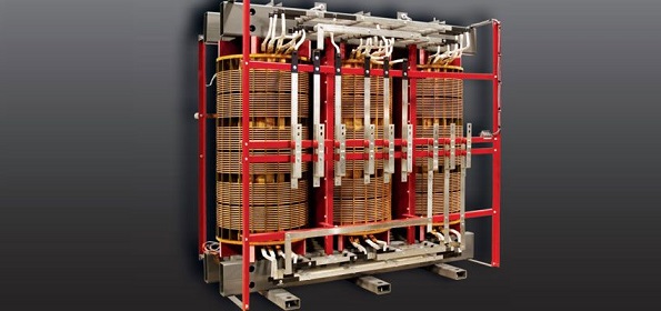
Transformers are made based on electromagnetic induction. It consists of an iron core stacked with silicon steel sheets (or silicon steel sheets) and two sets of coils wound around the iron core. The iron core and the coils are insulated from each other without any electrical connection. The coil connecting the transformer and the power supply side is called the primary coil (or the primary side), and the coil connecting the transformer and the electrical equipment is called the secondary coil (or secondary side). When the primary coil of a transformer is connected to an AC power source, changing magnetic lines of force are created in the iron core.
Since the secondary coil is wound on the same iron core, the magnetic line of force cuts the secondary coil, and an induced electromotive force must be generated on the secondary coil, causing a voltage to appear at both ends of the coil. Because the magnetic field lines are alternating, the voltage of the secondary coil is also alternating. And the frequency is exactly the same as the mains frequency.
It has been confirmed by theory that the voltage ratio between the primary coil and the secondary coil of the transformer is related to the turns ratio of the primary coil and the secondary coil, which can be expressed by the following formula: primary coil voltage/secondary coil voltage = primary coil turns/secondary coil turns Explain that the more turns, the higher the voltage. Therefore, it can be seen that the secondary coil is less than the primary coil, which is a step-down transformer. The opposite is a step-up transformer.
3. What types of transformer designs are there?
(1) According to the number of phases, there are single-phase and three-phase transformers
(2) According to the purpose, there are power transformers, special power transformers, voltage regulating transformers, measuring transformers (voltage transformers, current transformers), small power transformers (for low-power equipment), and safety transformers.
(3) According to the structure, there are two types: core type and shell type. Coils have double windings and multi-windings, autotransformers.
(4) According to the cooling method, there are oil-immersed and air-cooled.
4. What are the components of the transformer?
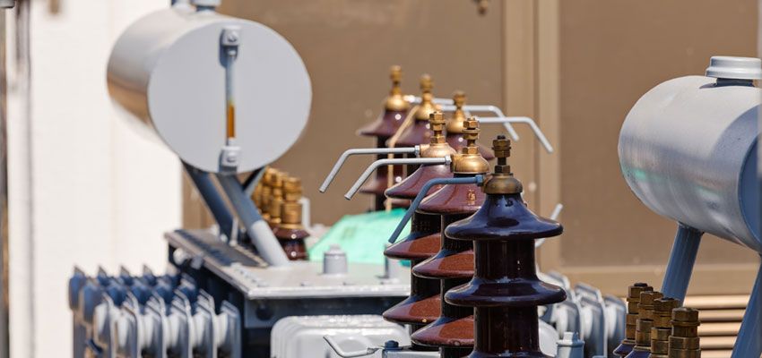
Transformer components are mainly composed of iron cores and coils, in addition to oil tanks, oil pillows, insulating sleeves and tap heads.
5. What is the use of transformer oil?
The role of transformer oil is:
(1) Insulation effect
(2) Heat dissipation
(3) Eliminate the arc effect
6. What is an autotransformer?
The autotransformer has only one set of coils, and the secondary coil is tapped from the primary coil. In addition to the transmission of electromagnetic induction, the secondary coil also transmits electricity. This transformer has more silicon steel sheets and copper wires than ordinary transformers. Less, often used to adjust the voltage.
7. How is the voltage regulator adjusted?
The structure of the voltage regulator is the same as that of the autotransformer, but the iron core is made into a toroidal coil and wound around the toroidal iron core.
The secondary coil tap uses a slidable brush contact to make the contact slide annularly along the coil surface to achieve smooth voltage regulation.
8. What is the current relationship between the primary coil and the secondary coil of the transformer?
When the transformer is running with load, the change of the secondary coil current will cause the corresponding change of the primary coil current. According to the principle of magnetic potential balance, the current of the primary and secondary coils is inversely proportional to the number of turns of the coil, the side with more turns is smaller, and the side with fewer turns is larger. It can be expressed by the following formula: primary coil current/secondary coil current = secondary coil turns/primary coil turns.
9. What is the voltage change rate of the transformer?
The voltage change rate of the voltage regulator is one of the main performance indicators of the transformer. When the transformer supplies power to the load, the voltage at the load end of the transformer will inevitably drop. Comparing the dropped voltage value with the rated voltage value, the percentage is the voltage change rate, which can be expressed by the formula; the voltage change rate = [(secondary rated voltage - Load terminal voltage) / secondary rated voltage] × 100%. When a normal power transformer is connected to a rated load, the voltage change rate is 4 to 6%.
10. How to ensure that the transformer has a rated voltage output?
Too high or too low voltage will affect the normal operation and service life of the transformer, so the voltage must be adjusted.
The method of voltage regulation is to lead out several taps in the primary coil and connect them to the tap head. The tap head changes the number of turns of the coil by rotating the contacts. As long as the position of the tap changer is turned, the required rated voltage value can be obtained. It should be noted that voltage regulation should usually be carried out after cutting off the load connected to the transformer.
11. What is the commonly used small transformer? Where is it applied?
Small transformers refer to single-phase transformers with a capacity of less than 1 kVA, which are mostly used as power transformers for electrical equipment control, power transformers for electronic equipment and power transformers for safety lighting.
12. What are the losses of the transformer during operation? How to reduce losses?
Losses in transformer operation include two parts:
(1) It is caused by the iron core. When the coil is energized, the eddy current and hysteresis loss in the iron core are caused due to the alternating magnetic field lines. This loss is collectively referred to as iron loss.
(2) It is caused by the resistance of the coil itself. When there is current passing through the primary coil and the secondary coil of the transformer, power loss will occur. This loss is called copper loss.
The sum of iron loss and copper loss is transformer loss, and these losses are related to transformer capacity, voltage and equipment utilization. Therefore, when selecting a transformer, the capacity of the equipment should be consistent with the actual usage as much as possible to improve the utilization rate of the equipment, and be careful not to run the transformer under light load.
13. What is the nameplate of the transformer? What are the main technical data on the nameplate?
The nameplate of the transformer indicates the performance, technical specifications and application occasions of the transformer, and is used to meet the user's selection. Usually, the main technical data to be paid attention to are:
(1) KVA of rated capacity. That is, the output capacity of the transformer in the rated state. Such as single-phase transformer rated capacity = U line × I line; three-phase transformer capacity = U line × I line.
(2) Rated voltage in volts. The terminal voltage of the primary coil and the terminal voltage of the secondary coil (when not connected to the load) are respectively marked. Note that the terminal voltage of the three-phase transformer refers to the line voltage U line value.
(3) Rated current amperage. Refers to the line current I line value that the primary coil and secondary coil allow long-term passage under the conditions of rated capacity and allowable temperature rise.
(4) Voltage ratio. Refers to the ratio of the rated voltage of the primary coil to the rated voltage of the secondary coil.
(5) Wiring method. Single-phase transformers have only one set of high and low voltage coils, which are only available for single-phase use, while three-phase transformers have Y/△ type. In addition to the above technical data, there are the rated frequency of the transformer, the number of phases, the temperature rise, the impedance percentage of the transformer, etc.
14. How to choose a transformer? How to determine the reasonable capacity of the transformer?
First of all, it is necessary to investigate the power supply voltage of the place where the electricity is used, the actual electricity load of the user and the conditions of the place, and then select one by one according to the technical data indicated on the transformer nameplate. Generally, the capacity, voltage, current and environmental conditions of the transformer should be comprehensively considered. Among them, the capacity should be selected. The transformer capacity should be selected according to the capacity, nature and use time of the user's electrical equipment to determine the required load. During normal operation, the power load of the transformer should be about 75-90% of the rated capacity of the transformer. During operation, if it is measured that the actual load of the transformer is less than 50%, the small-capacity transformer should be replaced. If the transformer's rated capacity is greater than the rated capacity of the transformer, the large transformer should be replaced immediately.
At the same time, when selecting the transformer, the voltage value of the primary coil of the transformer is determined according to the line power supply, and the voltage value of the secondary coil is selected according to the electrical equipment. It is best to choose a low-voltage three-phase four-wire power supply. This can provide power and lighting power at the same time.
For the selection of current, it should be noted that the load can meet the requirements of the motor when the motor starts (because the starting current of the motor is 4 to 7 times larger than that of the sinking operation).
15. Why can't the transformer be overloaded?
Overload operation refers to the operation of the transformer that exceeds the current value specified on the nameplate.
Overload is divided into normal overload and accident overload. The former refers to the increase in the user's power consumption under normal power supply conditions. It often increases the temperature of the transformer, promotes the aging of the transformer insulation, and reduces the service life. Therefore, Transformer overload operation is not allowed.
Under special circumstances, the overload operation of the transformer in a short time shall not exceed 30% of the rated load (winter), and shall not exceed 15% in summer.
16. What kinds of tests should the transformer do during operation?
In order to ensure the normal operation of the transformer, the following tests should be carried out frequently:
(1) Temperature test. Whether the operating state of the transformer is normal or not, the temperature is very important. The regulations stipulate that the upper oil temperature should not exceed 85C (ie, the temperature rise is 55C). Generally, transformers are equipped with special temperature measuring devices.
(2) Load determination. In order to improve the utilization rate of the transformer and reduce the loss of electric energy, in the operation of the transformer, the power supply capacity that the transformer can really bear must be determined. The measurement work is usually carried out during the peak period of electricity consumption in each season, and the clamp-type ammeter is used for direct measurement. The current value should be 70% to 80% of the rated current of the transformer. When it exceeds, it means overload and should be adjusted immediately.
(3) Voltage measurement. Regulations require that the voltage variation range should be within ±5% of the rated voltage. If this range is exceeded, taps should be used to adjust to bring the voltage within the specified range. Generally, a voltmeter is used to measure the terminal voltage of the secondary coil and the terminal voltage of the terminal user.
(4) Determination of insulation resistance. In order to keep the transformer in a normal operating state, the measurement of insulation resistance must be carried out to prevent insulation aging and accidents. When measuring, try to stop the operation of the transformer, and use the shaker to measure the insulation resistance value of the transformer. It is required that the measured resistance is not lower than 70% of the previously measured value. When the shaker is selected, the low-voltage coil can use a voltage level of 500 volts.
17. What is the polarity of the transformer? What is the role in practical use?
The polarity of the transformer is used to mark the relative relationship between the potentials of the coil ends of the primary winding and the coil ends of the secondary winding at the same time. Because the magnitude and direction of the electromotive force change at any time, at a certain moment, the primary and secondary coils must have two terminals that are high potential at the same time, and two terminals that are low potential at the same time. The high corresponding terminal is called the same polarity terminal of the transformer. It can be seen that the polarity of the transformer determines the winding direction of the coil, and when the winding direction changes, the polarity also changes. In practice, the polarity of the transformer is the basis for the parallel connection of the transformer. According to the polarity, it can be combined into a variety of voltage forms. If the polarity is reversed, a large short-circuit current will often occur, which will burn out the transformer. Therefore, when using the transformer, you must pay attention to the markings on the nameplate.
18. How to judge the polarity of the transformer?
When the nameplate of the transformer is unclear or it is an old transformer, it can be judged by testing. There are two methods:
(1) DC method.
When testing a single-phase transformer, pull in a 1.5-volt dry cell on the primary side, and then pull in a DC millivoltmeter on the secondary. When the switch K is closed, the needle swings in the positive direction (or the needle swings in the negative direction when the switch is opened), indicating that the positive end of the battery is of the same polarity, or the end of the same name. To test the polarity and level of three-phase transformers, the DC method is mostly used.
(2) Communication method.
Connect a pair of ends of the same name of the primary coil and the secondary coil with wires. Then pull in a low AC voltage between the AX primary coils for easy measurement. Use a voltmeter to measure the voltage V1 value between AX, the voltage V2 value between XX, and the voltage V3 value between ax. If the value of V2 is the difference between the voltages of V1 and V3, then Aa is the same-polarity terminal; if the value of V2 is the sum of the voltages of V1 and V3, then AX is the same-polarity terminal. Contents in Transformer Tour Inspection. Whether the sound of the transformer is normal; whether there is seepage and oil leakage; whether the oil mark and oil level are normal; whether there is gas inside the gas relay; whether the respirator is complete; whether the moisture-proof agent has failed and discolored; ; Whether the internal sound of the transformer is normal; whether the cable and lead bus are overheated, moved, deformed, etc.
Kingrun Transformer Instrument Co.,Ltd.


More Transformer Testers from Kingrun


