
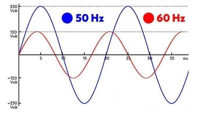
Electrical power systems around the world operate at either 50 Hz or 60 Hz, depending on regional standards. Most countries—including those in Europe, Asia, and Africa—use 220–240V at 50 Hz, while countries such as the United States, parts of Japan, and Saudi Arabia use 120/240V at 60 Hz. While this difference affects power generation and transmission systems, it has a significant impact on transformer design, size, losses, and long-term efficiency.
The fundamental transformer equation:
E = 4.44 × f × N × A × B
Where:
E = induced voltage
f = frequency
N = number of turns
A = core cross-sectional area
B = flux density
Key Insight: For a given voltage and power rating, increasing frequency (f) allows the transformer core area (A) to be smaller.
✅ Result: 60 Hz transformers are typically smaller and lighter than their 50 Hz counterparts for the same power rating.
Transformer iron (core) losses consist of:
Eddy Current Losses ∝ f²
Hysteresis Losses ∝ f
This means core losses increase significantly at 60 Hz:
For instance, a core that loses 100 W at 50 Hz might lose around 144 W at 60 Hz, assuming similar material and design.
Transformers operating at 60 Hz may require better core materials (e.g., cold-rolled grain-oriented silicon steel) to manage these losses.
Copper Losses (I²R) are generally similar between 50 Hz and 60 Hz systems for the same load.
However, core losses at 60 Hz increase total no-load losses, potentially reducing efficiency at light load conditions.
Increased losses at 60 Hz can lead to higher operating temperatures, which affects insulation aging and overall transformer life if not properly managed.
60 Hz transformers are more compact, which lowers material costs and allows for smaller enclosures and installations—advantageous for commercial and residential applications.
50 Hz transformers, while bulkier, run cooler and often have longer insulation life due to lower core loss and reduced operating stress.
Though not directly inside the transformer, the grid frequency impacts transformer performance via external circuit characteristics:
Inductive Reactance (X = 2πfL) is higher at 60 Hz, causing:
Higher voltage drop across transmission lines.
Increased short-circuit currents at the transformer terminals.
Skin Effect:
More pronounced at 60 Hz.
Raises effective resistance of transformer windings and busbars, increasing I²R losses and reducing efficiency slightly.
Transformers are frequency-specific. A 50 Hz transformer should never be operated at 60 Hz and vice versa unless explicitly designed for dual-frequency use. Otherwise:
Overfluxing may occur.
Excessive core saturation, overheating, and insulation failure risk.
For motors or transformers moved internationally, this is a critical installation concern.
| Application | 50 Hz Advantage | 60 Hz Advantage |
|---|---|---|
| Long-distance Transmission | Lower reactance, lower losses | — |
| Industrial Loads | Better stability at lower frequencies | Faster rotating motors |
| Transformer Size | Larger, cooler | Smaller, more compact |
| Efficiency | Higher at light load | Slightly better for motors |
| Maintenance Cycle | Longer insulation life | Requires better thermal design |
While 60 Hz transformers benefit from compact size and faster motor applications, they suffer from higher core losses, greater heating, and reduced efficiency in long-distance transmission environments. Conversely, 50 Hz transformers, though larger, offer better thermal performance, lower insulation stress, and are better suited for industrial or utility-scale use where load stability and long service life are priorities. Transformer design must always align with the system frequency to avoid operational inefficiencies or equipment damage.
Kingrun Transformer Instrument Co.,Ltd.


More Transformer Testers from Kingrun


