Not Just Measuring Resistance: Identify Various Transformer Faults by Winding Resistance Tester
It is well known that measuring the resistance of a transformer's windings using a DC resistance tester is an effective way to obtain resistance values. However, is this the only function of a DC resistance tester? Clearly not; we should also analyze abnormal resistance values to identify various faults in transformers. Below are three practical applications of using resistance values to analyze different transformer faults.
Diagnosis of Winding Breakage Faults
In one case, the direct current resistance imbalance rate between the low-voltage side 10kV lines of a transformer was found to be 2.17%, exceeding the national standard value of 1% by more than double. After identifying the defect, tightening was performed on the connection points of the lead wires and conductor poles, followed by several tracking tests, but the defect persisted.
Gas chromatography analysis indicated that the C2H2 content in the transformer exceeded the standard, rising from 0.2 µL/L to 7.23 µL/L, indicating the presence of discharge faults. However, it was noted from the maintenance records of this main transformer that two soldering attempts had been made without degassing treatment before the observed change in C2H2 levels. The levels of other gases were generally normal, and analysis using the three-ratio method showed no signs of overheating. Historical pre-test data indicated that, apart from the excessive direct current resistance imbalance, all other parameters were normal.
Upon analyzing the excessive direct current resistance, it was found that the resistance value of phase C was relatively high, raising suspicions of a break in the wire. Inquiry with the manufacturer revealed that this winding had 24 strands. Based on calculations, if one strand were broken, the resultant error would match the actual measurement error, leading to the diagnosis of a broken strand in phase C. Inspection of the hood confirmed that one strand in phase C was indeed disconnected.
Diagnosis of On-Load Tap Switch Faults
In another case, direct current resistance imbalance was observed on the 110kV side of a transformer, with significant resistance discrepancies between the direct current resistances of phase C and the various tap switches. The resistance differences between the tap switches of phases A and B ranged from 10 to 11.7 µΩ, while for phase C, the differences ranged from 4.9 to 6.4 µΩ and 14.1 to 16.4 µΩ, initially indicating an abnormality in the phase C circuit.
Analysis of the direct current resistance data for C0 (the circuit from terminal C to neutral point 0) suggested a low probability of defects in the winding itself or in the polarity and selection switches of the on-load tap device. Therefore, the fault was suspected to be within the switching switch. Examination of the switch hood revealed that a screw fixing one of the polarity points of the switching switch to the selection switch was broken, resulting in increased contact resistance at the zero point and causing abnormal direct current resistance values.
Diagnosis of No-Load Tap Switch Faults
During the acceptance testing of a transformer modified at a power repair factory, inconsistencies and chaos in the direct current resistance data of the no-load magnetic tap switches for phases A, B, and C were discovered, with the tap positions not corresponding to the measured resistance values.
It was found that the switch positions did not align with the indicator positions, and there was no neutral position. After readjusting and reassembling, the system returned to normal.
In conclusion, measuring direct current resistance can help identify various faults in transformers, including winding faults, soldering points, tap switches, insulation issues, and internal overheating. Therefore, we must fully utilize the capabilities of DC resistance testers and combine practical experience to diagnose different transformer faults, ensuring the healthy and stable operation of transformers.
Kingrun Transformer Instrument Co.,Ltd.


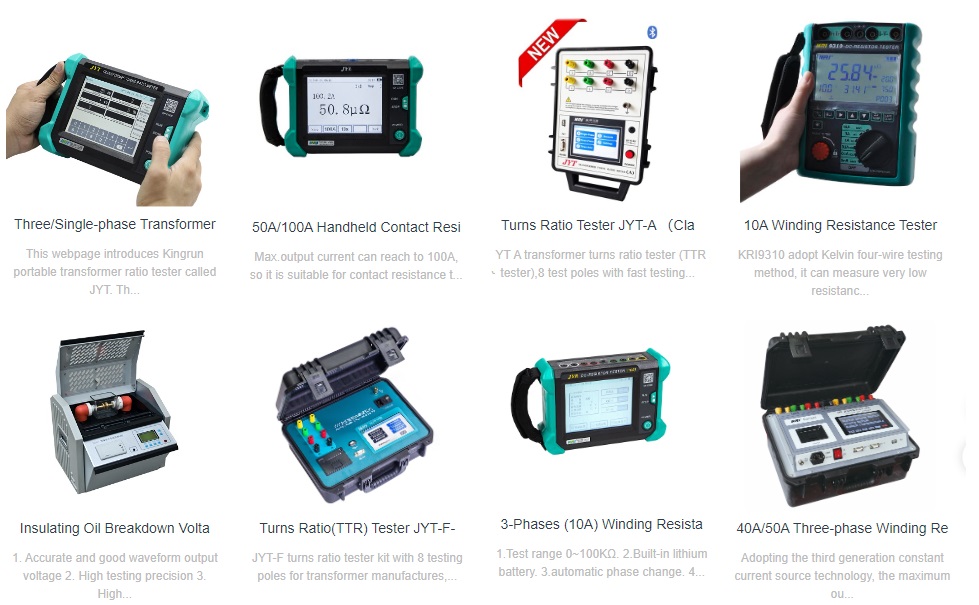
More Transformer Testers from Kingrun

