
The no-load and load tests of a transformer are conducted to assess its performance and operational condition, ensuring that the transformer can operate safely, stably, and efficiently under actual working conditions. These two tests focus on different operational states of the transformer, aiming to understand its core parameters and performance under various load conditions.
1. No-load Test
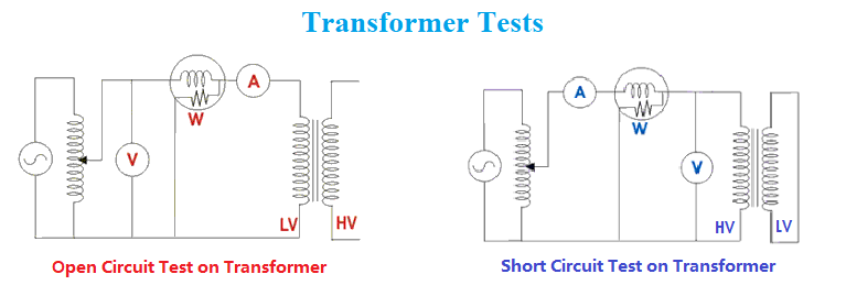
The no-load test, also called "no-load loss" or "excitation current test," is conducted by applying rated voltage to the primary winding while the secondary winding is open. The main purpose is to evaluate the core performance, no-load losses, and excitation current of the transformer. Specific reasons include:
Core Loss (No-load Loss) Measurement: Under no-load conditions, the losses in a transformer are primarily caused by hysteresis and eddy currents in the core. Measuring these losses helps assess the quality of the core material and the manufacturing process.
Excitation Current Measurement: By measuring the excitation current flowing into the primary side during no-load operation, one can understand the current required to maintain the magnetic flux in the transformer. This helps in analyzing the magnetic properties of the core.
Core Performance Evaluation: The no-load test also helps detect the saturation state of the core and its magnetization characteristics under different voltage levels, ensuring that the core operates within the designed range.
2. On-load Test
The on-load test is conducted by connecting a load to the secondary side of the transformer to assess its performance under actual working conditions. On-load testing can be further divided into short-circuit testing and load loss testing. The main reasons include:
Copper Loss (Load Loss) Measurement: The losses in a transformer under on-load conditions are mainly caused by the current in the windings, which results in copper losses. The on-load test can accurately measure the load losses of the transformer, allowing the assessment of its energy efficiency.
Transformer Efficiency Evaluation: The on-load test allows the calculation of the transformer’s efficiency under different load conditions, helping to understand energy losses and performance under various loads.
Voltage Regulation Characteristic Analysis: The on- load test also evaluates the voltage regulation characteristics of the transformer, i.e., the change in secondary voltage when going from no-load to full-load. This is critical for maintaining voltage stability in the power grid.
Short-circuit Impedance and Voltage Drop: The load test measures the short-circuit impedance and voltage drop of the transformer, which helps assess its response under fault conditions.
The no-load test of the transformer is to apply the rated voltage from the coil on one side of the transformer, and the other coils are open. Measure the no-load loss and no-load current of the transformer. The no-load current is expressed as a percentage of the rated current.
3. Through the no-load test, the following defects of the transformer can be found:
a. Poor insulation between silicon steel sheets.f. Misuse of high-consumption inferior silicon steel sheet or wrong design calculation.
The results of the phase separation measurement are judged according to the following principles:
1) Since the magnetic circuits of the ab phase and the bc phase are completely symmetrical, the measured losses P0ab and P0bc of the ab phase and the bc phase should be equal, and the deviation should generally not exceed 3%.
2) Since the magnetic circuit of the ac phase is longer than the magnetic circuit of the ab phase or the bc phase, the loss measured by the ac phase should be larger than that of the ab phase or the bc phase (35kV and below transformers are generally 30% to 40%, 110kV). and above transformers are generally 40% to 50%).
Example 1: A 90MVA, 220/121/38.5 transformer, I0=0.23%.
Single phase: pab=41.3kW=pa+pbpa=28kW pc=2.35pa=4.95pb
pac=93.8kW=pa+pcpb=13kW
pbc=79.1kW=pb+papc=65kW
The analysis found that the first turn (outlet end) of the C-phase low-voltage winding had an inter-strand short circuit, the low-voltage winding was 10 2.3×10.5 flat copper wires in parallel, and there were two wires on the outer layer to form a short circuit, and some of the copper wires were melted. A major accident.

JYW6100 Transformer Characteristic Power Tester

Kingrun Transformer Instrument Co.,Ltd.


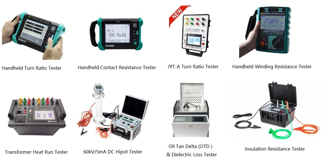
Please Check More Transformer/Substation Testers from Kingrun:

https://www.kritester.com/product/CT-PT-Analyzer.html
https://www.kritester.com/product/JYC-Dielectric-Loss-Tan-Delta-Tester.html
https://www.kritester.com/product/HV-Switchgear-Dynamic-Characteristic-Analyzer-JYK-II.html
https://www.kritester.com/product/PARTIAL-DISCHARGE-DETECTOR-TEV-ULTRASONIC-UHF-HFCT.html
https://www.kritester.com/product/Insulation-Resistance-Tester-for-transformer.html


