In high-voltage and power-distribution systems, the integrity and reliability of switchgear and control equipment are paramount. One critical indicator of connection quality and thermal performance is the main-circuit loop resistance. To ensure safe and stable operation under load, resistance measurements must be performed before and after the temperature rise (heat-run) test. This article outlines the proper measurement methods, acceptable variance thresholds, and reporting practices in compliance with transformer and switchgear testing standards.
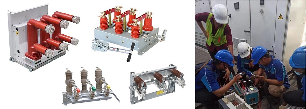
Main Circuit(Loop)
To compare the switchgear and control equipment that has undergone temperature rise testing (type testing) with the same model equipment subjected to factory testing, the main circuit resistance should be measured. The measurement methods are as follows:
- Use direct current (DC) to measure the voltage drop or resistance between each pole terminal.
- For enclosed switchgear and control equipment, special considerations should be taken.
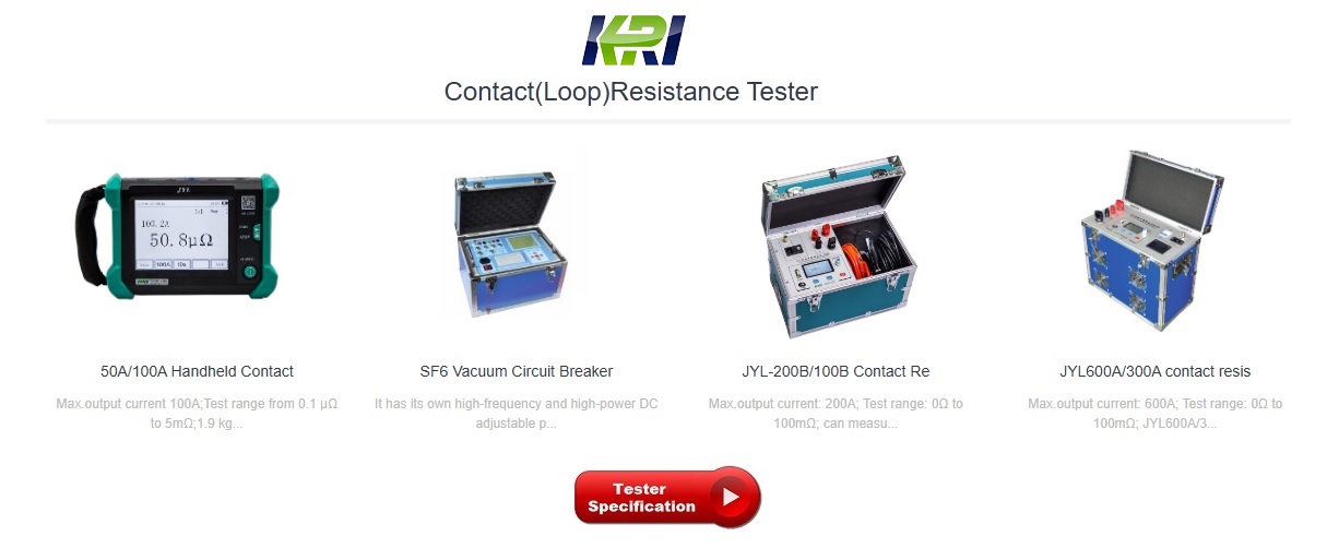
Test Current: Choose a current between 100A and the rated current.
Note: Relying solely on an increase in main circuit resistance is insufficient to confirm poor contact or connection issues. In such cases, it is recommended to repeat the test with a current as close as possible to the rated current to ensure accuracy.
Measurement Timing:
- Conduct the test once before the temperature rise test at ambient air temperature.
- After the temperature rise test, measure again once the equipment has cooled down to ambient air temperature.
- The difference between the resistance values measured in the two tests should not exceed 20%.
Reporting Requirements: The type test report should include the measured values of DC voltage drop or resistance, along with the general test conditions (current, ambient air temperature, measurement location, etc.)
Auxiliary Circuit(Loop)
1.Measurement of Resistance for Class 1 and Class 2 Auxiliary Contacts
- Take a sample of each type of Class 1 and Class 2 auxiliary contact and connect it in a resistive load circuit.
- Apply a DC source with an open-circuit voltage of 6V (with a tolerance of -15%) and pass a current of 10mA through it.
- Measure the resistance according to test method 2b in IEC61810-7.
Resistance Requirement: The resistance of closed Class 1 and Class 2 auxiliary contacts should not exceed 50 mΩ.
Note: Oxidation of contact materials may reduce effective current-carrying capacity, increasing contact resistance. This can cause non-conductivity in low-voltage circuits, while no issues may be seen in higher-voltage circuits. This test aims to verify contact performance under low-voltage conditions, accounting for the nonlinear behavior of resistance. The 50 mΩ limit is based on statistical data and has been widely accepted by users.
2.Measurement of Resistance for Class 3 Auxiliary Contacts
- Take a sample of a Class 3 auxiliary contact and connect it in a resistive load circuit.
- Apply a DC source with an open-circuit voltage of no more than 30mV, allowing a current of up to 10mA to pass through.
- Measure the resistance according to IEC61810-7.
This revised structure and translation provide clarity and ease of understanding for each testing。
Accurate loop-resistance testing following temperature-rise trials is essential for verifying contact integrity and thermal stability of switchgear and transformers. By adhering to controlled test currents, ensuring temperature stability, correcting for thermal effects, and staying within strict variance limits, engineers can confidently ascertain equipment reliability. Incorporating recognized standards such as IEC and IEEE practices enhances the rigor and comparability of results. Clear documentation in type test reports supports traceability and performance validation—ultimately contributing to safer and more dependable power-system operation.
Other Related Articles:
Why Does the Contact Resistance Testing Need 100A or Higher?
Hazards and Treatment of Excessive Contact Resistance of Circuit Breakers or HV Switches
How to measure the contact resistance without changing the circuit?
How to Correctly Test the Contact Resistance of HV Switchgear or Circuit Breaker?
Why Does Excessive Contact Resistance Occur In Electrical Secondary Circuits?
What is the Testing Checklist for 110kV/220kV Substation Acceptance and Maintenance Testing?
Kingrun Transformer Instrument Co.,Ltd.


More Transformer Testers from Kingrun