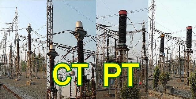
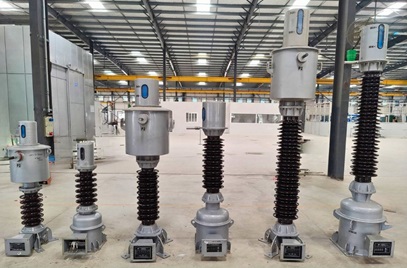
Why should CT and PT be checked and calibrated regularly?
Current Transformers (CTs) and Potential Transformers (PTs) are critical components in power systems, serving essential roles in measurement and protection. Regular inspection and calibration of CTs and PTs are vital for several reasons.
Firstly, they ensure the accurate operation of protection relays, preventing malfunctions such as false tripping or failure to trip during faults.
Secondly, for metering purposes, the accuracy of CTs and PTs directly affects the fairness of electricity billing between utilities and consumers—any deviation can lead to financial losses or disputes.
Additionally, over time, these transformers may experience issues such as core demagnetization, insulation degradation, or loose wiring connections. If left unchecked, these faults can result in inaccurate measurements or protection failures, potentially causing power outages.
National regulations and industry standards require periodic calibration of CTs and PTs to maintain system reliability and compliance. Therefore, routine inspection and precise calibration of these devices are essential for ensuring safe power system operation, safeguarding economic interests, and preventing equipment failures. This is especially important for power plants, substations, and large electricity consumers

The measurement of winding resistance for instrument transformers is similar in basic principles to that of power transformers, but there are some notable differences in methods and requirements due to differences in application, structure, and accuracy requirements. Here are some key distinctions:
Current and Voltage Requirements
For power transformers, a relatively higher test current can be used for winding resistance measurement, whereas in instrument transformers, especially current transformers, the test current must be limited to no more than 20% of the rated current to avoid coil heating, which could impact measurement accuracy.
Measurement Equipment
A single-arm bridge is often used to measure the primary winding resistance of voltage transformers, while a double-arm bridge is commonly used for secondary windings and for current transformer windings to achieve higher accuracy. If the secondary winding resistance exceeds 10Ω, a single-arm bridge can also be used.
Wiring Configuration
For power transformers, the non-tested winding is typically grounded during measurement, whereas for instrument transformers, the non-tested winding is left floating. Proper wiring configurations are critical to ensure precise measurements.
Discharge Requirements
Instrument transformer winding measurements require careful attention to the discharge process due to the higher inductance of the windings. Insufficient discharge before disconnecting the test terminals can generate overvoltages, potentially damaging winding insulation. Modern DC resistance testers usually have automatic discharge functions to prevent this.
Temperature Compensation
The results of winding resistance tests for both transformers and instrument transformers are generally temperature-compensated to a standard temperature for consistent comparison with historical data. However, due to the simpler winding structure of instrument transformers, temperature effects on results are usually less significant. Consequently, if there is minimal temperature variation, strict compensation may not be necessary.

1. DC Resistance Measurement Methods for Windings
- Primary Winding Measurement
For the primary winding of a voltage transformer, it is recommended to use a single-arm bridge, as the low resistance values can be accurately measured with this method.
- Secondary Winding Measurement
For the secondary winding of a voltage transformer and the primary or secondary winding of a current transformer, a double-arm bridge is advised. If the DC resistance of the secondary winding exceeds 10Ω, a single-arm bridge should be used instead.
- Use of DC winding resistance testers
A DC resistance tester can also be used for measurements. However, it is crucial to keep the test current below 20% of the rated current of the coil to prevent overheating, which could increase resistance and impact measurement accuracy.
2. Test Connections and Safety Requirements
- Connection Method
Connect the terminals of the winding under test to the bridge, leaving non-tested windings floating. When using a double-arm bridge or digital DC resistance tester, the current terminals should be positioned outside the voltage terminals.
- Precautions When Changing Connections
Disconnect the bridge’s power source before changing connections. Ensure that the winding under test is adequately discharged before disconnecting test terminals. Insufficient discharge before disconnection may cause overvoltage, potentially damaging the main insulation of the coil. Most digital DC resistance testing devices come with automatic discharge and warning functions to enhance safety.
- Measuring the Intermediate Transformer Winding in Capacitive Voltage Transformers
When measuring the DC resistance of the primary and secondary windings in capacitive voltage transformers, disconnect the primary winding from the voltage-dividing capacitor and the secondary winding from any external connections. If the primary winding and the capacitor are connected internally and cannot be separated, measurement of the secondary winding’s DC resistance may not be required.
3. Key Test Points
- Control of Test Current
The test current should not exceed 50% of the current derived from the rated load of the winding to avoid unnecessary heating of the coil.
- Data Stability
When windings have a high number of turns and high inductance, the displayed data on the DC resistance tester may take time to stabilize. Wait until the reading is stable before recording the value.
- Discharge Requirements
After testing, allow the device to discharge completely before disconnecting the test circuit to ensure safety.
- Recording Environmental Conditions
Document the ambient temperature and relative humidity at the time of the test, as these factors influence resistance readings.
- Temperature Conversion
Convert DC resistance values to a common temperature for comparison, which helps eliminate temperature variation effects on the measurement results.
4. Criteria for Judging Test Results
The measured DC resistance values should be compared to previous test results and those from similar equipment to confirm no significant discrepancies, ensuring the equipment’s status is within acceptable limits.
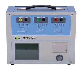
Kingrun's CT& PT Analyzer JYH-C

Related Articles:
The Most Complete Transformer Vector Group Collection with Winding Connection Diagrams
How Important is Transformer DC Winding Resistance?
Top 6 transformer winding resistance testers Worldwide (Including Prices)
How should Winding Resistance be Tested Differently on CT and PT?
What is the Difference between DC Resistance and Insulation Resistance and How to Test Them?
8 Tips to Improve the Accuracy of DC Resistance Measurement
Why is the Tested Winding Resistance Always Inaccurate? You May Have Overlooked These 6 Key Points
Kingrun Transformer Instrument Co.,Ltd.


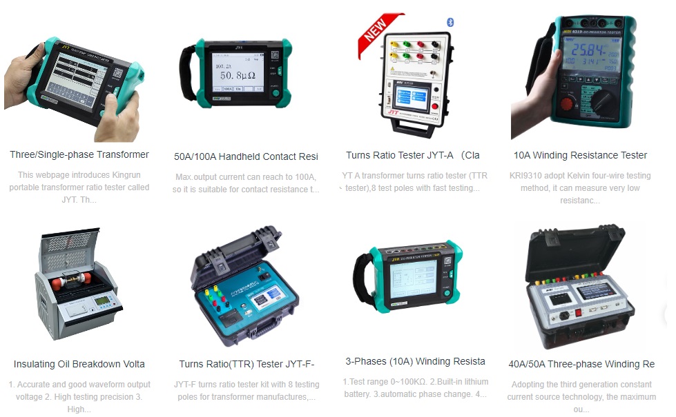
More Transformer Testers from Kingrun
