
A new approach will solve it. This method is useful for measuring contact resistance in complex mechanical assemblies. Contact resistance is defined as the ratio of the voltage across a contact to the current flowing through a pair of closed contacts. It conforms to Ohm's law. There is an interface between Metal 1 and Metal 2. The current I from the current source flows through this interface and can be read from the ammeter. The voltage drop on the interface can then be read from the voltmeter to U. The contact resistance value Rx can then be calculated.
Rx=I/I
Since the contact resistance varies with the environment and current passage, the measurement conditions should be close to the conditions of use. Accurate measurements must use four-terminal measurement technology and thermal EMF elimination technology. This indirect measurement method can be used to measure contact resistance or loop resistance. It requires three test points, three steps, and three formulas. This method has proven correct and can also be used to calibrate loop resistance standards.
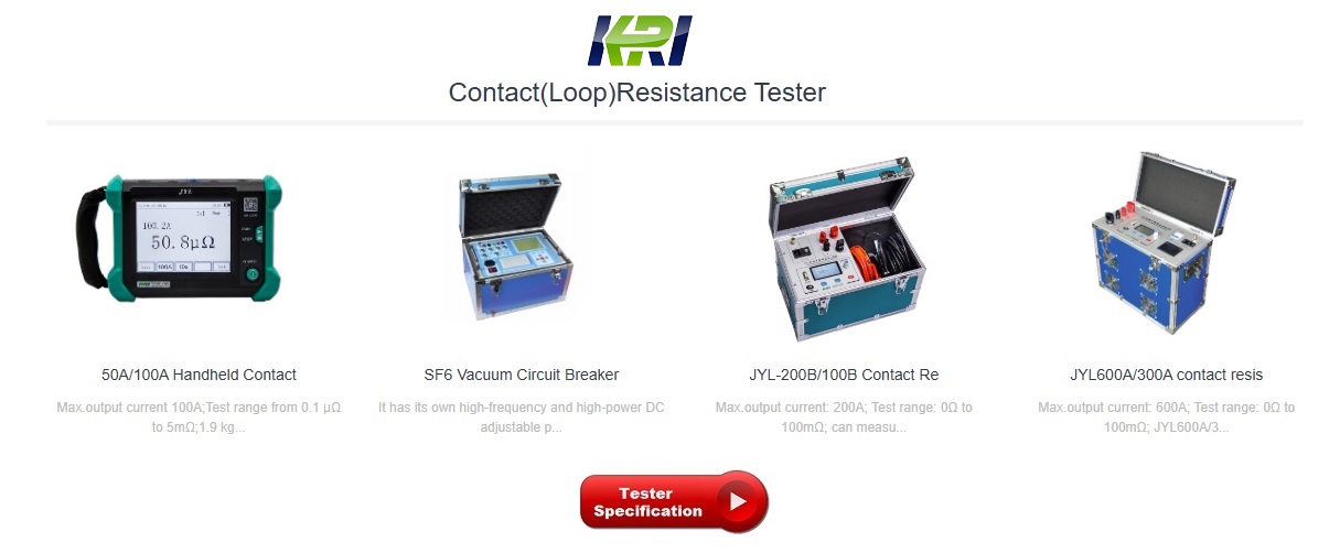
Typical method of contact resistance testing
The four-wire (Kelvin) DC voltage drop is a typical method for contact resistance testing with microohmmeters, which ensures a more accurate measurement by eliminating its own contact resistance and the resistance of the test leads.
The contact resistance test uses two current connections for injection and two potential leads for voltage drop measurement; The voltage cable must be as close as possible to the connection to be tested and always within the circuit formed by the connected current leads.
Based on the measurement of the voltage drop, the microprocessor-controlled micro-ohmmeter calculates the contact resistance, while eliminating the error that can be generated by the thermal EMF effect in the connection (thermal EMF is the small thermocouple voltage generated when two different metals are joined together) They will be added to the total voltage drop measured, and if they are not subtracted from the measurement by different methods (polarity reversal and averaging, direct measurement of thermal EMF amplitude, etc.), errors will be introduced in the contact resistance test.
If a low resistance reading is obtained when testing the contact resistance of a circuit breaker using a low current, it is recommended to retest the contact at a higher current. Why would we benefit from using higher currents? Higher currents will be able to overcome connection problems and oxidation on the terminals, and under these conditions, lower currents may produce false (higher) readings.
It is important to maintain consistent measurement conditions in contact resistance testing to be able to compare with previous and future results for trend analysis. Therefore, when making periodic measurements, the contact resistance test must be carried out in the same location, with the same test leads (always using the calibration cable provided by the manufacturer) and under the same conditions to be able to know when the connection, connection, soldering or equipment will become unsafe.
Kingrun Transformer Instrument Co.,Ltd.


More Transformer Testers from Kingrun


