What are the Installation and Testing Requirements for HV Switchgear?
Vacuum circuit breakers should utilize vacuum interrupters that have undergone aging tests, accompanied by relevant breaking type test reports. For circuit breakers operating at 40.5 kV and above, handling capacitive or inductive loads, SF circuit breakers should be used, along with corresponding breaking type test reports.
High-voltage switchgear must be selected from products with comprehensive "five protections" functions and reinforced insulation. The external insulation must meet the following criteria:
1) Clearance distance in air: ≥125 mm (for 12 kV), ≥360 mm (for 40.5 kV);
2) Creepage distance: ≥18 mm/kV (for porcelain insulation), ≥20 mm/kV (for organic insulation).
For circuit breakers rated 126 kV and above, the making and breaking time should not exceed 60 ms, with a recommended maximum of 50 ms. If the making and breaking time does not meet the fast operation time requirements of protective devices, priority should be given to ensuring the safety of the circuit breaker. A comprehensive withstand voltage test must be performed before the circuit breaker leaves the factory.

The handover acceptance of equipment must strictly comply with IEC 62271 standards; equipment that does not meet handover acceptance standards must not be put into operation.
Environmental conditions during the on-site installation of GIS equipment must be strictly controlled. Technical personnel from the operating unit must participate in the quality supervision of the GIS installation process, overseeing busbar installation, unit docking, and the cleanliness inside the casing to prevent contamination of the GIS internal insulation, which could lead to equipment accidents. Conditions should be created to conduct partial discharge measurements during the handover tests. For circuit breakers equipped with closing resistors, a breakdown AC withstand voltage test should be performed after new installations and major repairs.
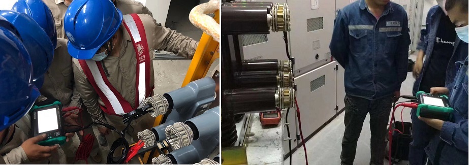
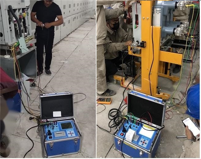
After new installations and major repairs, the mechanical travel characteristics of the circuit breaker must be measured and comply with the relevant technical requirements. This includes measuring mechanical travel characteristic curves, making and breaking times, the coordination between auxiliary switch transitions and main contact actuation times, and the pre-insertion time of closing resistors. Manufacturers must provide measurement methods for mechanical travel characteristics and factory test data, as well as connection devices for on-site testing.
If mechanical travel characteristic tests cannot be performed on-site, the manufacturer must provide factory test data and testing methods. In principle, factory tests must not replace handover tests. During operation, if the oil circuit breaker is severely low on oil for any reason, or if the gas pressure of the SF6 circuit breaker is abnormal, or if the pressure of the hydraulic (pneumatic) operating mechanism is abnormal, leading to a lockout of the circuit breaker, operation of the circuit breaker is strictly prohibited. Circuit breakers must have their low voltage action characteristics of the operating mechanism regularly checked before commissioning, after maintenance, and during operation to prevent failures due to inadequate low voltage characteristics.
When operating the circuit breaker, if there is excessive voltage drop in the control circuit power cable that does not meet the specified operating voltage, it should be replaced with a cable of larger cross-section to reduce the voltage drop, thus preventing failures due to excessive voltage drop in the power supply cable. The design department should also consider the voltage drop caused by cables during the design phase. Active vacuum testing of vacuum circuit breakers should be conducted to prevent accidents caused by declining vacuum levels.

If effective methods for measuring vacuum levels cannot be adopted, the vacuum interrupter must pass a withstand voltage test before being put into operation after new installation, major repairs, or pre-tests to prevent accidents due to vacuum decline. Vacuum circuit breakers should select high-performance vacuum interrupters based on usage conditions, and manufacturers should provide aging test reports for the interrupters. Strengthen the detection and testing of closing resistors to prevent failures caused by defects in the closing resistor.
During factory tests, handover tests, and preventive tests of circuit breaker products, the resistance value of the closing resistor and the coordination relationship between the main contact and the closing resistor contact should be tested. For 500 kV SF circuit breakers with closing resistors, the overvoltage levels during switching should be verified annually based on changes in the power system. If the operating overvoltage levels meet regulatory requirements without the closing resistor, technical modifications to remove the closing resistor can be considered during major and minor repairs to enhance the reliability of the high-voltage circuit breaker.
When installing parallel voltage-sharing capacitors for circuit breakers, prevent oil leaks due to "axial forces," and any leaks found should be addressed or the components replaced. To prevent faults caused by improper coordination between making/breaking times and protective device action times, measures should be taken to ensure that the making/breaking times of the circuit breaker are consistent with the requirements for the safety and stability of the power system. Thus, extending the action time of protective devices to resolve this issue is not recommended; instead, reliable measures should be implemented by the circuit breaker itself.
The promised making/breaking times of the circuit breaker products should be verified against the results of type tests; according to IEC 62271 requirements, the design value for making/breaking times should not exceed 60 ms, with a recommendation of not more than 50 ms. Testing of the following two parameters should be emphasized:
1) Making and breaking time of the circuit breaker. The test results should comply with the requirements in the product technical conditions.
2) Coordination between the conversion time of the auxiliary switch and the action time of the main contacts.
To prevent faults in switchgear caused by control circuit power sources and secondary circuits, all DC operation power supplies must ensure that the terminal voltage at the closing electromagnet coil of the circuit breaker is not lower than standard requirements. For the terminal voltage of the closing coil of the electromagnetic operating mechanism, it should be no less than 80% of the rated operating voltage when the closing current is less than 50 kA (peak); and no less than 85% of the rated operating voltage when the closing current is equal to or greater than 50 kA (peak); and should not exceed 110% of the rated operating voltage to ensure the reliability of closing and reclosing actions.
If the above requirements cannot be met, improvements should be made according to the specific situation. For substations at voltage levels of 220 kV and above, there should be two reliable power sources. Newly built substations should not use silicon rectifier closing power supplies and capacitor energy storage tripping power supplies. Newly installed or repaired disconnect switches must undergo circuit resistance testing, and active porcelain insulator flaw detection and contact pressure testing should also be conducted. For new equipment and equipment after major repairs containing SF6 density relays, the density relays must be calibrated and qualified before commissioning.
Other Related Articles:
Why Does the Contact Resistance Testing Need 100A or Higher?
Hazards and Treatment of Excessive Contact Resistance of Circuit Breakers or HV Switches
How to measure the contact resistance without changing the circuit?
How to Correctly Test the Contact Resistance of HV Switchgear or Circuit Breaker?
Why Does Excessive Contact Resistance Occur In Electrical Secondary Circuits?
What is the Testing Checklist for 110kV/220kV Substation Acceptance and Maintenance Testing?
Kingrun Transformer Instrument Co.,Ltd.


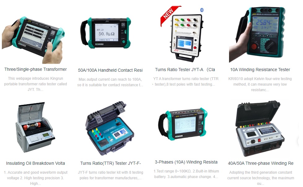
More Transformer Testers from Kingrun


