
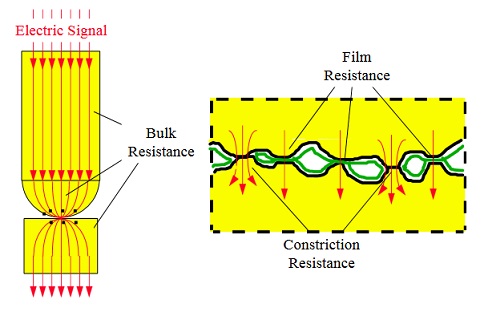
Contact resistance is the resistance formed when two conductors are in contact or connected. When the contact surface becomes smaller and the contact surface is oxidized, the contact resistance will increase sharply. The size of the contact resistance is proportional to the temperature, and the resistance is related to the temperature. As the temperature rises, the resistance increases. As a result, the contact resistance and the temperature will increase in a cycle. The contact resistance of the current loop causes the secondary loop resistance of the current transformer to increase, the measurement error of the current transformer increases, and the voltage drop of the contact resistance of the voltage loop increases.
1 Analysis of the influence of contact resistance on the electrical secondary circuit
1.1 The influence of contact resistance in the current loop
There are many current loops in the secondary current loop of the power system that belong to the plug and socket connection. Such a connection method will greatly increase the contact resistance at the connection, which poses a great threat to the correct operation of the relay protection. The current ratio of the current loop is increased, and the excessive contact resistance will also cause equipment damage, fire and other accidents due to heat.
For example, during the overhaul of generator No. 1 in Datang thermal power plant in October 2021, it was found that the joint of the first-phase current transformer on the high-voltage side of No. 1 transformer was loose, causing the maximum loop resistance to reach 42Ω, but the minimum value was less than 2Ω, and the current was calculated according to the most serious case. For the 10% error curve of the transformer, when the main transformer differential protection has the maximum passing short-circuit current, the secondary circuit voltage of the current transformer is 4800V, and the volt-ampere characteristic curve of the current transformer is saturated at about 300V. Calculate the error of the current transformer with the secondary rated current of the transformer 2A, the secondary circuit voltage is about 500V, which is far more than the volt-ampere characteristic curve of the current transformer by 300V. From the analysis, it can be seen that the current circuit connected by the plug and socket cannot meet the requirements of the site at all, and must be modified during shutdown. Even after adjusting the connection part at that time, the DC resistance of the current transformer is qualified, but because the lead wire of the connection is long, the lead wire has to withstand the wind and rain outdoors, and the people on the transformer can easily reach the lead wire, and the rain and moisture enter. The rust and oxidation inside the connector will aggravate the increase of the contact resistance. At the generator end of the engine room and the neutral point current transformer at the connection, personnel can easily reach the lead wire, and the vibration of the generator foundation may cause a substantial change in the contact resistance of the connection at any time.
1.2 Influence of contact resistance in voltage secondary circuit
The low-voltage side of the voltage transformer is basically a fuse and an air switch, both of which have the problem of contact resistance. The biggest impact is the metering loop of the generator watt-hour meter. When the contact resistance voltage drop of the fuse box and the air switch is 1V, and the low-voltage rated voltage of the voltage transformer is 57V, it will cause 1.75% of the electricity billing loss. In particular, the 110kV bus voltage transformer has a lot of load, the current of the secondary circuit is large, and the contact resistance voltage drop of the fuse box and the air switch is larger, which directly affects the measurement of on-grid electricity. Because the generator busbar voltage transformer and the high-voltage busbar voltage transformer are separated for protection, measurement, and measurement, the error of the voltage required by the protection can be higher, so the impact on the protection can be ignored.
Secondly, the 6kV power bus voltage transformer of the power plant calculates the power of the low-voltage power transformer of each power plant. The measurement, measurement and protection of the 6kV busbar voltage transformer are not separated from the secondary circuit, so the load of the 6kV busbar voltage transformer insurance and air switch is very large, and the influence of the contact resistance voltage drop on the protection, measurement and measurement cannot be ignored. If the load current of the 6kV busbar voltage transformer fuse and the air switch is calculated at 0.5A, and the contact resistance is calculated at 20Ω, then the voltage drop caused by the contact resistance will reach about 10V, which is not the most serious situation. The 6kV busbar voltage transformer fuse and the air switch have large contact resistance due to the large secondary load, and it is easy to overheat to cause the fuse to blow and the switch to trip. Most 6kV voltage transformers are equipped with secondary plugs. If the plugging and unplugging contact is not good, there is a high possibility of serious consequences. For example, the generator measurement PT should be used in the parallel circuit in the same period, and its measurement meter, electric energy meter, and some protections are also used. The load current reaches 0.5A, and the contact resistance reaches 40-50Ω according to the above-mentioned contact resistance, and the loop voltage measurement error will be If the voltage is 20-25V, the parallel connection of generators will cause serious asynchronous grid connection.
1.3 Influence of contact resistance in DC circuit
The influence of contact resistance in the DC circuit is mainly the contact resistance of the relay contacts. Due to environmental conditions such as temperature, humidity, pollution, etc., the contacts of the relay will be oxidized and rusted, and the contacts of the relay will be deformed due to vibration and other reasons. These will cause a sharp change in the contact resistance of the contacts of the relay. The oxide film of some relay contacts is too thick. on. The coil resistance of some relays is very small. For example, the current starting coil and the current holding coil of the anti-jump relay are generally 1~2Ω. The current holding coil is connected in series with the contacts of the relay. If the contact resistance of the contact is too large, it will affect the performance of the relay. The contact resistance of the relay contact increases, which may cause the contact to burn and stick when a large current is passed, and the contact does not return after the relay coil is de-energized.
Datang Luoyang Thermal Power Co., Ltd. once had two 110kV busbar voltage transformer low-voltage switching intermediate relays due to the large flow of current, which caused the contacts to burn and stick. When the busbar was out of service, because the two busbar voltage transformers were always in parallel, When the busbar tie switch is turned on, the running busbar is reversely charged to the power failure busbar through the two parallel voltage transformers, and the voltage transformer insurance of the two busbars is blown. In the relay protection of the power system, the accident that the relay contacts are slightly stuck due to the large contact resistance of the relay contacts has occurred many times. Now with the development of microcomputer protection, the current relay protection personnel have less and less understanding of electromagnetic relays, and do not pay enough attention to the inspection of electromagnetic relays. There are many phenomena, so the change of the contact resistance of the relay is basically incomplete.
The influence of contact resistance in the DC circuit is also reflected in the switch of the DC system power switch and the power switches and power fuses of each branch. When the contact resistance of the power switch and power fuse of each branch of the DC system is relatively large, when multiple devices are closed and tripped at the same time in the branch, the DC voltage at the tripping and closing coil of the device will be directly affected. If the contact resistance of the branch circuit power switch and the power fuse is 5Ω, and the 6kV busbar low voltage protection action occurs, assuming that there are 10 motor switches to be tripped, and the trip current of each switch is 1A, the voltage drop of the contact resistance will reach 50V at this time. It is likely to affect the normal tripping of the equipment.
2 Countermeasures and measures for the large contact resistance of the secondary circuit
(1) Take advantage of the shutdown opportunity to change the plug-and-socket connection of the generator transformer to the direct connection of the terminal block. A rain-proof and dust-proof junction box is installed at the connection between the current transformer and the outside, and the connection between the internal current transformer circuit and the outer circuit of the sealed female is connected through the terminal block in the junction box. Disconnect the relevant leads on the terminal block when the current transformer needs to be disconnected for maintenance. The comprehensive protection of motor protection and factory transformer protection is plug-in type. Every time the comprehensive protection is unplugged and then inserted into the comprehensive protection, the connection must be disconnected on the terminal block. The resistance of the AC circuit should not change too much before and after plugging and unplugging. .
All electromagnetic current relays should measure the resistance of the AC circuit of the relay before and after unplugging and inserting the relay. Insist that all wiring terminals of the current loop must be tightened each time. Insist on periodic measurements of the connection resistance of the current loop.
Adhere to the daily temperature measurement and maintenance of the current terminal block and the connection of the plug and socket.
(2) Regularly measure the voltage drop and load current of the generator bus voltage transformer, the high voltage bus voltage transformer metering circuit, the 6kV bus voltage transformer fuse and the fuse box of the air switch and the air switch. After each voltage transformer circuit failure Also check the voltage drop of the fuse box and air switch in time.
(3) The contact reliability inspection of the electromagnetic relay and the mechanical inspection of the internal contacts of the relay should be carried out according to the requirements of the inspection procedures. If the contact deformation is found, the relay should be replaced in time. If the adjustment still does not meet the requirements, the relay should be replaced. The electromagnetic relays inside should be carefully inspected in accordance with the inspection procedures for electromagnetic relays.
In each major repair, check the contact resistance of the DC system power switch knife switch and each branch power switch and power fuse, which meets the requirements of the maintenance regulations. Measure the contact resistance voltage drop of the DC system power switch knife switch and each branch power switch and power fuse as needed.
3 Conclusion
According to the universality and seriousness of the large contact resistance in the electrical secondary circuit, it is necessary to strengthen the measurement and maintenance of the circuit resistance in the maintenance of the electrical secondary equipment. Add items to measure secondary loop resistance in on-site maintenance procedures and work instructions, and strengthen the analysis of dangerous points with large loop resistance.
Other Related Articles:
Why Does the Contact Resistance Testing Need 100A or Higher?
Hazards and Treatment of Excessive Contact Resistance of Circuit Breakers or HV Switches
How to measure the contact resistance without changing the circuit?
How to Correctly Test the Contact Resistance of HV Switchgear or Circuit Breaker?
Why Does Excessive Contact Resistance Occur In Electrical Secondary Circuits?
What is the Testing Checklist for 110kV/220kV Substation Acceptance and Maintenance Testing?
Kingrun Transformer Instrument Co.,Ltd.


More Transformer Testers from Kingrun


