
1.What is "Loop resistance" in substation and why is it called that?
(Loop Resistance) refers to the total resistance of all conductive parts within a complete current loop.
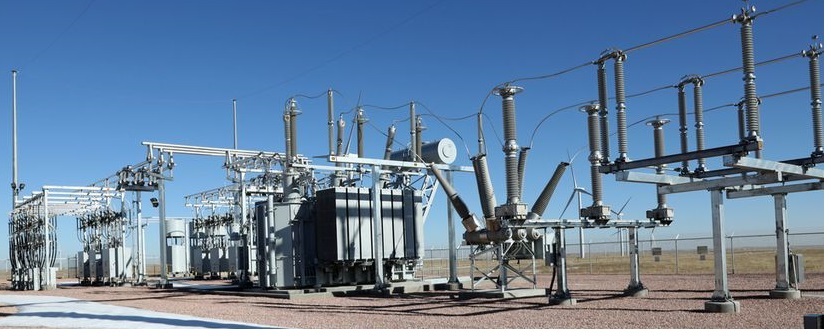
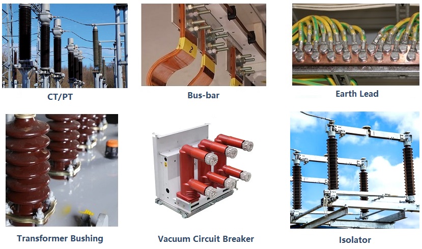
In substations or high-voltage systems, this “loop” usually refers to the current path that starts from the circuit breaker main contact, passes through conductive clamps, busbars, connection lines, current transformers, isolating switches, and finally returns to the other end, forming a closed loop.
The term “loop” is used because the current starts from the power source, flows through the load or conductive path, and then returns to the source — forming a closed circuit.
Loop resistance measurement focuses on the total resistance that hinders current flow within this loop. It encompasses the resistance of internal conductive components, connection points, and conductors themselves — a key electrical parameter in high-voltage circuits.
Identify Connection Defects:
Excessive contact resistance (due to oxidation, loosened bolts, etc.) can cause local overheating, melting of contacts, or even arcing faults.
Ensure System Stability:
Over-limit loop resistance causes excessive voltage drop, reduces power transmission efficiency, and may trigger protection misoperation or equipment derating.
Verify Equipment Condition:
Pre-commissioning or post-maintenance testing confirms installation and repair quality; periodic testing tracks equipment aging and wear trends.
Strict Power Isolation:
Disconnect all power sources, perform grounding and voltage verification before testing to prevent electric shock or equipment damage.
Clean Contact Surfaces Thoroughly:
Use sandpaper or cleaning agents to remove oxidation and grease, ensuring firm contact between test probes and the test points.
Use Dedicated High-Voltage Instruments:
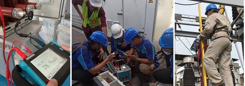
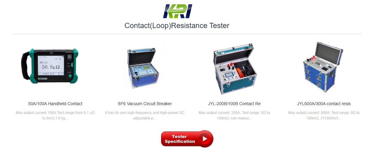
Employ a high-current loop resistance tester (typically 100 A / 200 A DC output) for accurate measurement; ordinary instruments lack sufficient precision.
Isolate Non-Tested Branches:
Disconnect unrelated branches or parallel components to prevent current division that would cause abnormally low readings.
Maintain Safe Distance:
Keep an appropriate safety distance from energized high-voltage equipment to avoid induced voltage hazards.
4. What problems might you encounter when using a loop resistance tester
The loop resistance tester(Contact Resistance Tester,circuit resistance tester) is an instrument that is used very frequently in our power industry, but in fact, this instrument will encounter some problems during use, how do we solve these problems?
According to the conventional design principle of loop resistance testers (Contact Resistance Tester,circuit resistance tester) found in the field test, they will have a common problem: when the tester voltage wiring loop has poor contact or open circuit, the tester will display a value, and the following situations will occur about the value:
1, the voltage loop is open, the test site has no strong electric field interference, in this case, because the differential mode voltage of the amplifier input is basically 0, so the test value displayed by the instrument is close to 0, if the tester has enough field test experience, We can judge from it that the instrument voltage loop test line is abnormal, and after the instrument voltage loop test line is abnormally discharged, we can obtain the final correct test result;
2, the voltage loop contact is poor, in most cases the circuit breaker terminal in the long-term operation of the rear end of the outer surface of the sub-row will produce oxide film or oil film, when the loop resistance meter voltage test clamp clamp to such a terminal block may produce poor contact, both the voltage test line clamp itself to produce a certain contact resistance, the contact resistance value to the voltage sampling circuit internal resistance value when the equivalent will have a serious impact on the test results.
3. The voltage loop is open circuit or poor contact, and the test site has strong electromagnetic interference, such as the busbar is charged, at this time, the charged bus bar passes through the capacitance of the air as the medium, interfering with the two voltage test lines of the tester, and the differential mode voltage appears at both ends of the voltage collection line of the loop tester due to the effect of interference.
Other Related Articles:
What is the Testing Checklist for 110kV/220kV Substation Acceptance and Maintenance Testing?
Kingrun Transformer Instrument Co.,Ltd.


More Transformer Testers from Kingrun


