How to correctly test the DC winding resistance of transformer windings?
The winding resistance measurement is to check the welding quality of the inner wire, lead and coil, whether the specifications of the wire used in the coil conform to the design, and whether the current-carrying parts such as the tap changer and bushing are in good contact.
1. The resistance of each winding of the transformer should be measured on the wire terminals of each winding; when the three-phase transformer winding is connected in a Y connection mode without a neutral point, its wire resistance should be measured, such as AB, BC, CA; if there is a neutral When the point is drawn out, its phase resistance, such as AO, BO, CO, should be measured; but for the distribution transformer with yn connection and low voltage of 400V with a large proportion of neutral point lead resistance, its line resistance (Ub, bc) should be measured. , ca) and the resistance of the neutral point to a line end, such as ao. When the windings are D-connected, the phase resistance should be measured for those drawn from both the head and the end: the line resistance should be measured for the test sample of a closed triangle.
 2. For windings with tap changers, the winding resistance should be measured under all tap changers. When the on-load voltage regulating transformer has positive and negative excitation switches (polarity selector), the winding resistance of all taps should be measured in one direction, and only 1 to 2 taps can be measured in the other direction. When measuring the winding resistance, the off-excitation tap-changer should make the positioning device enter the designated position; the on-load tap-changer should be operated electrically.
3. When measuring the winding resistance, the winding temperature must be recorded accurately; when the winding resistance is measured after the transformer leads are assembled, the body should not be parked in a place where the air flows quickly and the surrounding air temperature changes greatly. Record the ambient temperature at this time: total After the assembly is completed, for dry-type transformers, the winding temperature should take the average value of not less than three points on the surface of the windings; for oil-immersed transformers, after the oil temperature has stabilized, inject at least 2/2/2 of the temperature into the thermometer seat of the tested transformer. Transformer oil above 3 depth, and insert a thermometer; at this time, the temperature of the top layer of the oil can be used as the winding temperature, and the average temperature of the oil should be taken as the winding temperature for large transformers.
4. According to the calculated value of the winding resistance in the product technical data, reasonably select a DC resistance tester or a special bridge (accuracy should not be lower than 0.2); the requirements are as follows:
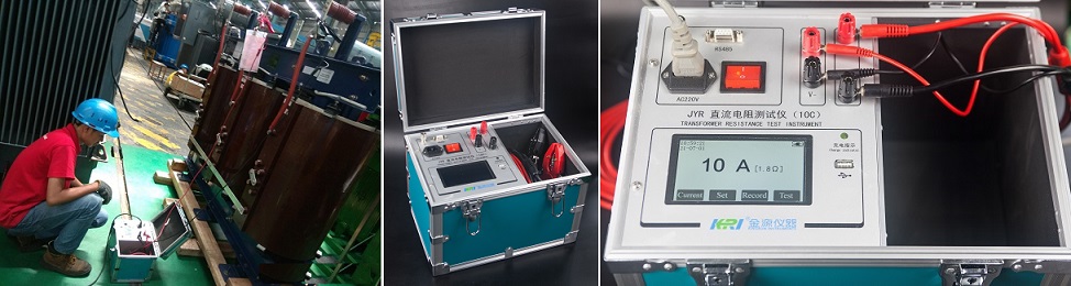
(1) Check the instrument and select the test current of the DC resistance tester according to the instruction manual of the DC resistance tester and the size of the winding resistance.
(2) The lead-out terminals of each winding must be in an open state; if there is an open delta-connected winding, it should be opened and not connected.
(3) When measuring the winding resistance of the transformer with tap, the on-load voltage regulating transformer does not need to cut off the measuring circuit, but only needs to restart the instrument.
(4) For non-excitation voltage regulating transformers, when changing the tap position, the power supply must be cut off; for D/D connected transformers, the tap can be changed phase by phase without cutting off the power supply.
(5) When the tested product is a five-column transformer with a large capacity and the low voltage is D-connected, the DC resistance measurement should use the magnetization method to shorten the measurement time; after the test, attention should be paid to demagnetization.
(6) When measuring, be sure to wait for the influence of the winding self-inductance to be minimized, and then read the data, otherwise it will cause a large error.
(7) After each measurement, the measurement circuit must be completely discharged and confirmed before proceeding to the next step.
2. For windings with tap changers, the winding resistance should be measured under all tap changers. When the on-load voltage regulating transformer has positive and negative excitation switches (polarity selector), the winding resistance of all taps should be measured in one direction, and only 1 to 2 taps can be measured in the other direction. When measuring the winding resistance, the off-excitation tap-changer should make the positioning device enter the designated position; the on-load tap-changer should be operated electrically.
3. When measuring the winding resistance, the winding temperature must be recorded accurately; when the winding resistance is measured after the transformer leads are assembled, the body should not be parked in a place where the air flows quickly and the surrounding air temperature changes greatly. Record the ambient temperature at this time: total After the assembly is completed, for dry-type transformers, the winding temperature should take the average value of not less than three points on the surface of the windings; for oil-immersed transformers, after the oil temperature has stabilized, inject at least 2/2/2 of the temperature into the thermometer seat of the tested transformer. Transformer oil above 3 depth, and insert a thermometer; at this time, the temperature of the top layer of the oil can be used as the winding temperature, and the average temperature of the oil should be taken as the winding temperature for large transformers.
4. According to the calculated value of the winding resistance in the product technical data, reasonably select a DC resistance tester or a special bridge (accuracy should not be lower than 0.2); the requirements are as follows:
(1) Check the instrument and select the test current of the DC resistance tester according to the instruction manual of the DC resistance tester and the size of the winding resistance.
(2) The lead-out terminals of each winding must be in an open state; if there is an open delta-connected winding, it should be opened and not connected.
(3) When measuring the winding resistance of the transformer with tap, the on-load voltage regulating transformer does not need to cut off the measuring circuit, but only needs to restart the instrument.
(4) For non-excitation voltage regulating transformers, when changing the tap position, the power supply must be cut off; for D/D connected transformers, the tap can be changed phase by phase without cutting off the power supply.
(5) When the tested product is a five-column transformer with a large capacity and the low voltage is D-connected, the DC resistance measurement should use the magnetization method to shorten the measurement time; after the test, attention should be paid to demagnetization.
(6) When measuring, be sure to wait for the influence of the winding self-inductance to be minimized, and then read the data, otherwise it will cause a large error.
(7) After each measurement, the measurement circuit must be completely discharged and confirmed before proceeding to the next step.
5. Conversion of resistance: The unbalance rate of three-phase resistance is calculated by taking the difference between the maximum value and the minimum value of three-phase resistance as the numerator and the average value of three-phase electricity as the denominator; the unbalance rate of three-phase resistance should conform to IEC TS 60076 standard.
When the unbalance rate of three-phase line resistance is less than 1%, the conversion between line resistance and phase resistance is carried out according to formula (1) and formula (2):
Y-junction Rxg=Rxn/2 ------------------------------------ (1)
D-junction Rxg=1.5RXD -----------------------------------(2)
When the unbalance rate of three-phase line resistance is greater than 1%, the conversion of line resistance and phase resistance is carried out according to formulas (3) to (9):
Y-connection Ra=(Rab+Rac-Rbc)/2 ---------------------------- (3)
Rb=(Rab+Rbc-Rac)/2 ---------------------------- (4)
Rc=(Rbc+Rac-Rab)/2 ---------------------------- (5)
D-junction (a-y, b-z, c-x) Ra=(Rac-Rp)-[RabRbc/(Rac-Rp)] --------------- (6)
Rb=(Rab-Rp)-[RacRbc/(Rab-Rp)] ---------------(7)
Rc=(Rbc-Rp)-[RabRac/(Rbc-Rp)] --------------- (8)
Rp=(Rab+Rbc+Rac)/2 ----------------------------(9)
where:
Rab, Rbc, Rac - line resistance of each phase;
Ra, Rb, Rc——phase resistance of each phase;
Rxg - three-phase line resistance;
Rxn - phase resistance of three phases.
When converting the winding resistance at different temperatures, the following formula is used:
Rθ=Kt·Rt
Kt=(T+θ)/(T+t)
where:
Kt——resistance temperature conversion coefficient;
Rθ, Rt——resistance when the temperature is θ°C, t°C;
T——coefficient, copper winding is 235, aluminum winding is 225
Other Related Articles:
The Most Complete Transformer Vector Group Collection with Winding Connection Diagrams
How Important is Transformer DC Winding Resistance?
Top 6 Transformer winding resistance testers Worldwide (Including Prices)
How should Winding Resistance be Tested Differently on CT and PT?
What is the Difference between DC Resistance and Insulation Resistance and How to Test Them?
8 Tips to Improve the Accuracy of DC Resistance Measurement
Why is the Tested Winding Resistance Always Inaccurate? You May Have Overlooked These 6 Key Points
Kingrun Transformer Instrument Co.,Ltd.


More Transformer Testers from Kingrun


