
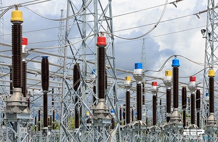
Disconnect switch is one of the most used electrical appliances in high-voltage switching appliances. As the name implies, it plays an isolation role in the circuit. Its working principle and structure are relatively simple, but due to the large amount of use and high requirements for work reliability, it has a great impact on the design, establishment and safe operation of substations and power plants. The main feature of the knife switch is that it has no arc extinguishing ability, and can only divide and close the circuit without load current.
Choice of disconnect switch:
The disconnect switch is arranged on the main wiring to ensure that the line and equipment are separated from the live part by an obvious fracture. Since the disconnect switch has no arc extinguishing device and has low breaking capacity, when operating the disconnect switch, the switching operation sequence must be followed. That is to say, when power is supplied, the bus-side disconnect switch is closed first, the line-side disconnect switch is closed second, and the circuit breaker is closed last.
Disconnect switch configuration:
1. Both sides of the circuit breaker should be equipped with disconnect switch, so as to form an obvious fracture and isolate the power supply during the maintenance of the circuit breaker.
2. Ordinary transformers whose neutral point is directly grounded should be grounded through the disconnect switch.
3. A set of disconnect switch should be used together for the arresters and voltage transformers on the busbar to ensure the safety of electrical appliances and busbar maintenance, and 1-2 sets of grounding switches should be installed on each busbar.
4. The arrester connected to the outgoing wire of the transformer or the neutral point may not be equipped with an disconnect switch.
5. When the user side of the feeder line has no power supply, the side of the circuit breaker leading to the user may not be equipped with an disconnect switch. But in order to prevent lightning overvoltage, it can also be installed.
Common faults and treatment of disconnect switch
1. The role of high voltage disconnect switch
The high-voltage disconnect switch has the function of isolating voltage, and can be used for some switching operations that do not generate arcs, such as opening and closing arresters, reactors, etc., or cooperate with circuit breakers to perform non-energized operations; during power outages or other maintenance work, the high-voltage disconnect switch can cut off the power outage part. and live parts to ensure the safety of operators; in some special power supply systems, the high-voltage disconnect switch can switch some circuits to change the operation mode of the power supply system.
2. Common faults of high voltage disconnect switch
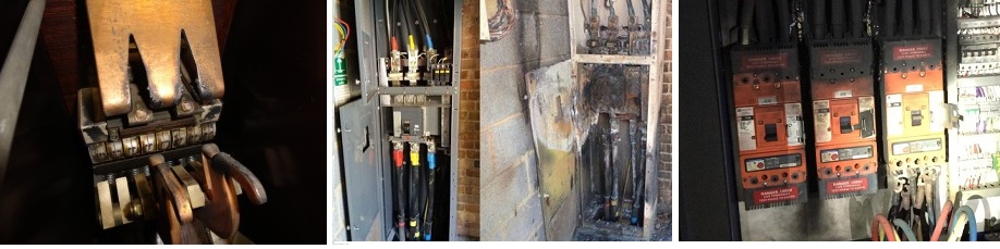
Common faults of high-voltage disconnect switch include disconnect switch overheating faults, insulation porcelain bottle breaking faults, and conductive parts rusting. Among them, the overheating fault is the most common defect in the operation of the high-voltage disconnect switch. After the overheating fault of the disconnect switch occurs, when the operating current reaches 60% of the rated value, abnormal heating has already occurred, which is a problem that cannot be found in debugging and maintenance before commissioning.
3. Cause analysis of overheating fault of high voltage disconnect switch
There are three reasons for the overheating fault of the disconnect switch:
① During installation and maintenance, too much conductive paste is used. In fact, it is not that the more conductive paste, the better the conductivity. Excessive thickness of the conductive paste will increase the distance between the metal contact parts, thereby reducing the conductivity.
②The contact surface of the high-voltage disconnect switch is oxidized, which increases the contact resistance. The greater the contact resistance, the more pronounced the heat generation. This thermal action exacerbates oxide film formation and burn deposition, which ultimately results in overheating failure.
③The electrical conductivity of the connection part of the high-voltage disconnect switch is reduced. For example, the loosening of the bolts at the fixed contact parts, the infiltration of rainwater and dust into the contact surface to make it oxidize, and the galvanic corrosion caused by the contact of the copper and aluminum conductive parts, etc., can cause abnormal heating of the disconnect switch.
4. Solutions for overheating faults of high-voltage disconnect switch
There are three ways to deal with the excessive heat of the disconnect switch:
(1) When the contacts of the disconnect switch are overheated, the contamination on the moving and static contacts should be cleaned up according to the technical specifications. At the same time, wipe the metal parts of the contacts to a bright state, and apply conductive paste according to the specifications.
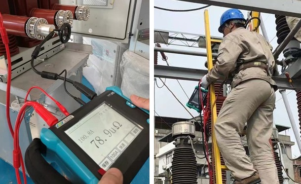
(2) The contact surface is oxidized. When overhauling, treat the metal contact part to keep the contact surface flat and have metal brightness; apply an appropriate amount of power grease, and then measure the contact resistance of the disconnect switch.
(3) When the dynamic and static contacts are in poor contact, the bolts should be pressed during installation and maintenance, and electrical grease should be applied to the contact parts to improve their electrical conductivity and prevent corrosion or oxidation of the contact parts.
① The excessively thick conductive paste will reduce the conductivity of the contacts. In fact, it is a problem caused by inferior conductive paste from an electrical point of view. Inferior conductive paste is used for the connection, not only will not play a role in reducing the resistance, but will cause the resistance to increase.
Common faults and treatment of disconnect switch
Inferior conductive pastes will flow, crack, or even solidify and agglomerate at high temperatures, which will increase the contact resistance by 25 times or even 70 times. However, high-quality conductive pastes retain their shape after high temperature, and are still delicate, which can play a very important role in connecting joints. Good resistance reduction and protection.
Common faults and treatment of disconnect switch
② High-quality conductive paste is used at the bolt, which can not only enhance conductivity, prevent corrosion and oxidation, but also inhibit loosening and stress fatigue caused by thermal expansion and contraction and vibration.
Summary of Frequently Asked Questions about disconnect switch
1. What are the common faults?
Answer: Common faults of disconnect switch are:
(1) The contact part is overheated.
(2) Porcelain insulation damage and flashover discharge.
(3) Refuse to pull and close.
(4) Wrong opening and closing.
2. What is the cause of the overheating of the contact part of the disconnect switch during operation?
Answer: The disconnect switch overheats during operation, which is mainly caused by heavy load, increased contact resistance, and not fully closed during operation.
3. What are the reasons for the increase in the contact resistance of the disconnect switch?
Answer: The reason for the increase in contact resistance is that the repulsion force at the contact between the blade and the blade is very large, and the blade is not tightly closed, which causes the surface to oxidize and increases the contact resistance. Secondly, the disconnect switch will cause arcs during the pulling and closing process, burn the contacts, and increase the contact resistance.
4. How to judge whether the disconnect switch contacts are overheated?
Answer: It can be judged according to the color change of the contact part of the disconnect switch or the color of the temperature test piece, and it can also be determined according to the darkening degree of the color of the blade. It is generally determined according to the results of infrared temperature measurement.
5. How to deal with overheating of disconnect switch contacts and contacts?
Answer: When it is found that the contacts and contacts of the disconnect switch are overheated, first report the dispatch, try to reduce or transfer the load, strengthen monitoring, and then deal with it according to different wiring:
(1) Double busbar wiring. If a busbar side knife switch is overheated, put the overheated disconnect switch out of operation through the inverted busbar, and power off for maintenance.
(2) Single bus connection. Its load must be reduced, monitoring should be strengthened, and measures should be taken to cool it down. If conditions permit, stop using it as much as possible.
(3) Switching of available bypass breakers with bypass breakers.
(4) If the line-side disconnect switch is overheated, the treatment method is basically the same as that of the single bus, and the power outage maintenance should be arranged as soon as possible. During the maintenance period, the load should be reduced and monitoring should be strengthened.
(5) Open-loop operation of one and a half circuit breaker wiring is possible.
(6) For the overheated contacts and contacts of the disconnect switch on the bus side, after the disconnect switch is pulled out, after on-site inspection, if the safety distance for live work is met, the down-conductor joint on the bus side can be removed with electrolysis and then dealt with.
6. How to check and deal with the failure of the electric operation of the disconnect switch?
Answer: After the electrical operation of the disconnect switch fails, first check whether there is any error in the operation, and then check whether the operation power circuit and power supply circuit are in good condition, and whether the fuse is blown or loose. Whether the electrical blocking circuit is normal.
7. How to deal with the welding deformation of disconnect switch contacts, damaged insulators, and severe discharge?
Answer: In these situations, the power should be cut off immediately, and the monitoring should be strengthened before the power cut.
8. How should the disconnect switch refuse to open or close?

Answer:
(1) Due to mechanical failures such as shaft pin falling off, wedge bolt withdrawal, cast iron fracture, or electrical circuit failure, the cutter bar may be disconnected from the operating mechanism, causing the disconnect switch to refuse to close. At this time, an insulating rod should be used for operation. , or in the case of ensuring personal safety, use a wrench to turn the shaft of each phase disconnect switch.
(2) Refuse to trip. When the disconnect switch cannot be opened, if the operating mechanism is frozen, you can shake it gently and observe the supporting porcelain bottle and various parts of the mechanism, so as to find out the obstacle according to where the deformation and displacement occur. If the obstacle occurs in the contact part of the disconnect switch, it should not be forcibly pulled away, otherwise the supporting porcelain bottle may be damaged and cause a serious accident. At this time, the operation mode of the equipment can only be changed to deal with it.
9. How to deal with the disconnection switch not in place?
Answer: The disconnect switch is not in place, most of which are caused by the corrosion of the mechanism, the jam, the maintenance and debugging are not adjusted properly, etc. If this happens, the disconnect switch can be opened and then closed. For the 220KV disconnect switch, it can be pushed in with an insulating rod, and if necessary, a power failure treatment should be applied. The high-voltage disconnect switch should be overhauled 1-2 times every 2 years.
Other Related Articles:
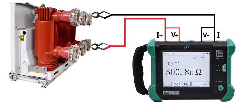
Why Does the Contact Resistance Testing Need 100A or Higher?
Hazards and Treatment of Excessive Contact Resistance of Circuit Breakers or HV Switches
How to measure the contact resistance without changing the circuit?
How to Correctly Test the Contact Resistance of HV Switchgear or Circuit Breaker?
Why Does Excessive Contact Resistance Occur In Electrical Secondary Circuits?
What is the Testing Checklist for 110kV/220kV Substation Acceptance and Maintenance Testing?
Kingrun Transformer Instrument Co.,Ltd.


More Transformer Testers from Kingrun


