
The DC winding resistance tester can measure transformers of various capacities, provided that the tester’s technical parameters (such as maximum test current and measurement range) match the DC resistance characteristics of the transformer under test.
The transformer capacity directly affects the winding DC resistance: generally, the larger the capacity, the greater the conductor cross-sectional area of the winding, and the smaller the DC resistance. For example, for large power transformers above 1000 kVA, the winding resistance may be in the milliohm range, while for small distribution transformers of tens of kVA, the resistance may reach several ohms. As long as the tester’s measurement range covers the expected winding resistance range and the maximum output current is sufficient to overcome the winding inductance (ensuring stable readings), transformers of different capacities can be accurately tested.

Since the resistance and inductance characteristics vary greatly between transformers of different capacities, the following phenomena may occur during measurement and should be carefully observed:
Fast stabilization of readings:
Small-capacity transformers have fewer turns and lower inductance, so the magnetization process after the DC current is applied is short. The reading usually stabilizes within a few seconds without noticeable fluctuation.
Relatively high resistance values:
Due to the smaller conductor cross-section, the DC resistance typically ranges from 0.1 Ω to 10 Ω (depending on material and turns). The readings fall within the mid-to-high resistance range, so precision issues in low-resistance measurement are not a concern.
Abnormal phenomenon – excessively high resistance:
If the measured resistance greatly exceeds the design or historical value (e.g., 10 Ω measured instead of the expected 2 Ω), possible causes include open circuit, loose connection, or conductor oxidation due to long-term overheating. The winding integrity should be further inspected.
Slow stabilization of readings:
Large-capacity transformers have many turns, thick conductors, and high inductance (tens to hundreds of henries). The magnetization process takes longer—up to several minutes. Recording data before stabilization will yield underestimated resistance values (because current has not fully stabilized, and (R = U/I)).
Extremely low resistance, easily affected by interference:
The DC resistance is usually 0.001 Ω to 0.1 Ω, which is highly sensitive to contact resistance and external electromagnetic interference. For instance, an oxidized or loose test clamp may introduce 0.005 Ω of contact resistance, causing significant reading error. Nearby running motors or transformers can induce AC interference, making readings fluctuate (e.g., 0.008 Ω–0.012 Ω).
Abnormal phenomenon – excessive phase unbalance:
For three-phase transformers, the resistance unbalance should be ≤ 2% (≤ 1% for large units). If unbalance exceeds this limit (e.g., A = 0.008 Ω, B = 0.012 Ω, C = 0.009 Ω), potential causes include inter-turn short circuit, tap changer contact failure, or uneven conductor material, requiring immediate inspection.

To ensure accurate results and safe operation, the following precautions should be taken according to transformer capacity:
Select the proper winding resistance tester:
For small transformers (< 100 kVA), choose testers with output currents of 1 A–10 A to prevent insulation stress. For large transformers (> 500 kVA), use high-current testers (10 A–100 A) to reduce magnetization time and improve accuracy in low-resistance measurement.
Check test connections and contact resistance:
Use thick copper test leads (≥ 4 mm²), clean the contact points with sandpaper, and tighten firmly. For milliohm-level measurements, use the four-terminal method (Kelvin connection)—separating current and potential leads to eliminate contact resistance error.
Eliminate external interference:
Disconnect the transformer completely from the grid (open both HV and LV breakers and isolators) and fully discharge the winding. For large units, allow several minutes for discharge due to stored capacitance. Shut down large electrical equipment within a 5 m radius (motors, welders, etc.) to avoid magnetic interference.
Small-capacity transformers:
Apply the rated test current, wait 3–5 seconds, and record when the value is stable. Compare with factory or historical data; if resistance differs by > 5% without cause, check for winding issues.
Large-capacity transformers:
Wait until the display shows a stable value (many instruments indicate stability). Repeat measurement 2–3 times at the same tap position; if deviation ≤ 0.5%, take the average as the final result. Larger deviations (> 1%) suggest poor contact or interference.
Prevent winding overheating:
DC current generates (Q = I^2Rt) heat. For large transformers, prolonged testing (> 10 minutes) can overheat windings and damage insulation. Always turn off current immediately after testing and discharge the winding using a grounding rod for at least 5 minutes until no spark appears.
Ensure insulation safety:
Before testing, measure insulation resistance using a megohmmeter (for a 10 kV transformer, (R_{\text{ins}} ≥ 100 MΩ)). If insulation is low, do not perform DC winding resistance testing—risk of short circuit or tester damage.
Avoid excessive test current for small units:
Applying high current (e.g., 100 A) to small or dry-type transformers may cause insulation breakdown. Follow the rule test current ≤ 1/10 of rated winding current (e.g., rated 50 A → test ≤ 5 A).
Single transformer:
Compare measured values with design or historical data. If deviation ≤ 5% (≤ 2% for large transformers) and phase unbalance within limits (≥ 1000 kVA → ≤ 1%, 100–1000 kVA → ≤ 2%, < 100 kVA → ≤ 4%), results are acceptable.
Multiple identical units:
When testing several transformers of the same model, compare their average values. If one unit differs by more than 3% from the average, investigate its winding and tap changer for abnormalities.
Related Articles:
The Most Complete Transformer Vector Group Collection with Winding Connection Diagrams
How Important is Transformer DC Winding Resistance?
Top 6 transformer winding resistance testers Worldwide (Including Prices)
How should Winding Resistance be Tested Differently on CT and PT?
What is the Difference between DC Resistance and Insulation Resistance and How to Test Them?
8 Tips to Improve the Accuracy of DC Resistance Measurement
Why is the Tested Winding Resistance Always Inaccurate? You May Have Overlooked These 6 Key Points
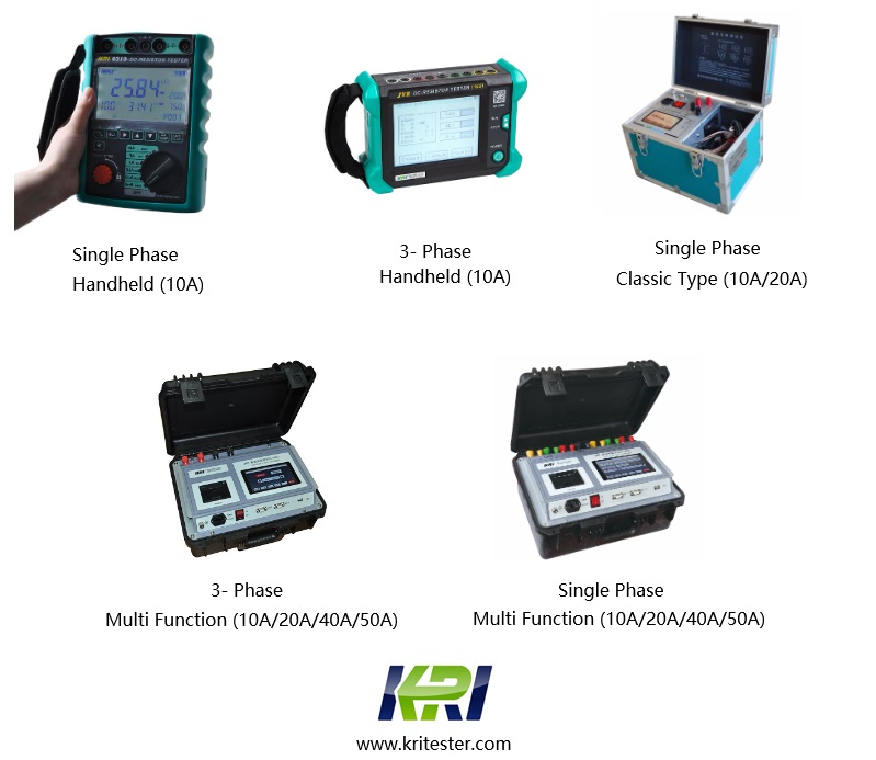
Kingrun Series DC winding resistance testers
Kingrun Transformer Instrument Co.,Ltd.


More Transformer Testers from Kingrun


