Case Study --- Find Transformer Faults by DC Winding Resistance Testing
Through direct resistance measurement, it is possible to check the welding or connection quality of the transformer leads, whether the winding is short-circuited or open between turns, and whether the tap-changer is in good contact.
Case 1: A 16000kVA, 6.3kV transformer, the three-phase unbalance rate of the low-voltage winding before treatment was 2.82%, the three-phase of the secondary winding was separated, and the DC resistance was measured respectively, the B was 7.8% larger than the A and C phases, and the inspection found that The lead wire of the B-phase winding is poorly welded, one of the three flat copper wires is broken, and 7-8 layers of white cloth tapes are wrapped to burn black. After reprocessing, the DC resistance is normal, and the three-phase unbalance rate is reduced to 0.005%.
Case 2: For a 31500kV, 10kV transformer, the unbalance rate of DC resistance at the factory is 3.6%, it is 2.5% before operation, and 2.7% during pre-test. After a sudden short circuit, the unbalance rate was measured to be 3%. After 5 times of impact closing, the measured DC resistance unbalance rate was 42.8%. After inspection, it was found that:
1) The 2nd turn-to-turn short circuit at the lower outlet of the low-voltage 1-branch A-phase coil, where the insulation and spacers are burnt.
2) The axial and radial displacement of the short-circuit turn winding is about 20mm.

Case 3: A 120000kVA, 220kV transformer has been in operation for 25 years. In 1991, abnormal DC resistance was found, and the unbalance rate reached 4.2%.
Measure the contact resistance of the connector at the outlet end of the low-voltage winding, and find that the B and C ends have increased from 10 uΩ to 300uΩ. The inspection found that the nut and the screw on the two connectors of the low-voltage winding B and C lead wires are melted. Nuts and washers have burn marks and melting points.
Case 4: For a 2000kVA, 63kV transformer, the DC resistance test results found that at tap position 9, the DC resistance deviation was 9.8%. The inspection found that the spring pressure of the on-load voltage regulating switch was insufficient, the screws were not tightened well, and the mechanical switch of the switch was not in place. The polarity switch is in virtual contact with the common point K, and the contacts have arc burn marks, and the DC resistance is balanced after treatment.
Case 5: A SFPSL-120000/220 transformer has been put into operation for 18 years, and all previous test results including DC resistance are normal. After a surface flashover accident of a 110kV side CT, the transformer tripped and burst into flames. When analyzing the DC resistance test results, it was found that the unbalance rate of each phase resistance complied with the requirements of the full regulations. In the test results of the first half year of the accident, although the three-phase DC resistance on the medium voltage side was balanced, it was not the same as that of previous years at the same temperature. Compared with the average test value, each phase is increased by about 8.15% (both high and low voltage are not more than 2%), indicating that there is a bad contact defect in the neutral point bushing on the medium voltage side, but no analysis is added after the test, and there is no current in normal operation. Passed, the chromatogram cannot reflect until an accident occurs.
 Case 6: A 120MVA, 220kV transformer suddenly trips during operation of light and heavy wattage protection and differential protection, oil injection, oil chromatographic analysis is arc discharge, and involves the characteristics of solid insulation. The three-phase DC resistance of the high-voltage winding is unbalanced, and A is about 12% larger than the two-phase B and C. Lifting the transformer shell found that the A-phase high-voltage I coil was short-circuited between the turns of the 5th segment from top to bottom, and it was blown. Why is the DC resistance of the winding only increased by 12% after the inter-turn short circuit of the winding is blown? This is determined by the winding structure. The winding of the transformer is a high-low-high structure, that is, the outermost is the high-voltage I coil, the middle is the low-voltage coil, and the innermost is the high-voltage II coil. The high-voltage I and high-voltage II are connected in series to form a high-voltage winding. together, and then in series with the high voltage II.
The turns of A1O1 or A2O2 are equal, accounting for about 1/4 of the turns of AO1.
It is assumed that the resistance of each segment has the following relationship:
RAO1=RAO2=4RA2O2=2RO1O=4RAA1/3
Under normal conditions:
R (HV)=RO1O+RAO1/2=RAO1
After A1O1 accident fuse
R (HV)=RO1O+RAA1/2+RA2O2
That is, the resistance of the high-voltage winding after the accident is about 12.5% larger than the resistance under normal conditions.
In the same way, it can be seen that the high-voltage I short circuit occurs between turns, the wire is blown, and the high-voltage winding resistance will increase by about 27%. For ordinary high-low structure transformers, the inter-turn short-circuit wire is blown in the high-voltage large area, and the high-voltage winding resistance increases by about 80%. According to the above experience and calculation, according to the resistance change, the fault interval can be roughly judged. Of course, there are also very few cases, after the short circuit between turns, the wires are not all blown, and the DC resistance of the coil does not change significantly.
Related Articles:
The Most Complete Transformer Vector Group Collection with Winding Connection Diagrams
How Important is Transformer DC Winding Resistance?
Top 6 transformer winding resistance testers Worldwide (Including Prices)
How should Winding Resistance be Tested Differently on CT and PT?
What is the Difference between DC Resistance and Insulation Resistance and How to Test Them?
8 Tips to Improve the Accuracy of DC Resistance Measurement
Why is the Tested Winding Resistance Always Inaccurate? You May Have Overlooked These 6 Key Points
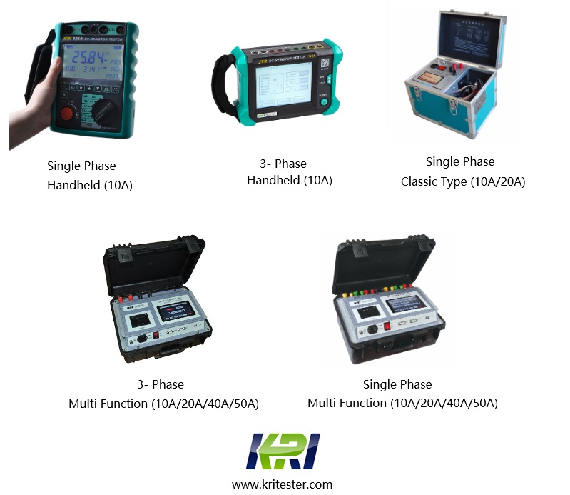
Kingrun Series DC winding resistance testers


Kingrun Transformer Instrument Co.,Ltd.


More Transformer Testers from Kingrun


